Power supply circuit and electronic appliance therewith

a power supply circuit and electronic appliance technology, applied in the direction of static indicating devices, instruments, basic electric elements, etc., can solve the problems of large switching noise attributable, large chip size, narrowing the tolerance range of the supplied voltage, etc., to eliminate brightness unevenness among leds

Inactive Publication Date: 2007-03-01
SHARP KK
View PDF9 Cites 4 Cited by
  • Summary
  • Abstract
  • Description
  • Claims
  • Application Information

AI Technical Summary

Benefits of technology

[0027] With the configuration according to the present invention, when it is recognized that at least one of the LEDs cannot be fed with a current at the specified level, the set current level is automatically changed so that currents at equal levels are passed through all the LEDs. This helps eliminate brightness unevenness among the LEDs. That is, even when the supplied voltage lowers, without the need for a step-up circuit, all the LEDs can be made to emit light with equal brightness.

Problems solved by technology

Requiring a step-up circuit as described above, the power supply circuit disclosed in JP-A-2004-166342 mentioned above, disadvantageously, requires an unduly large chip size for the power supply circuit as a whole, and also produces large switching noise attributable to a component, such as a coil, used to build the step-up circuit.
This, however, disadvantageously narrows the tolerated range for the supplied voltage.

Method used


Image

  • Power supply circuit and electronic appliance therewith
  • Power supply circuit and electronic appliance therewith
  • Power supply circuit and electronic appliance therewith

Examples


first embodiment

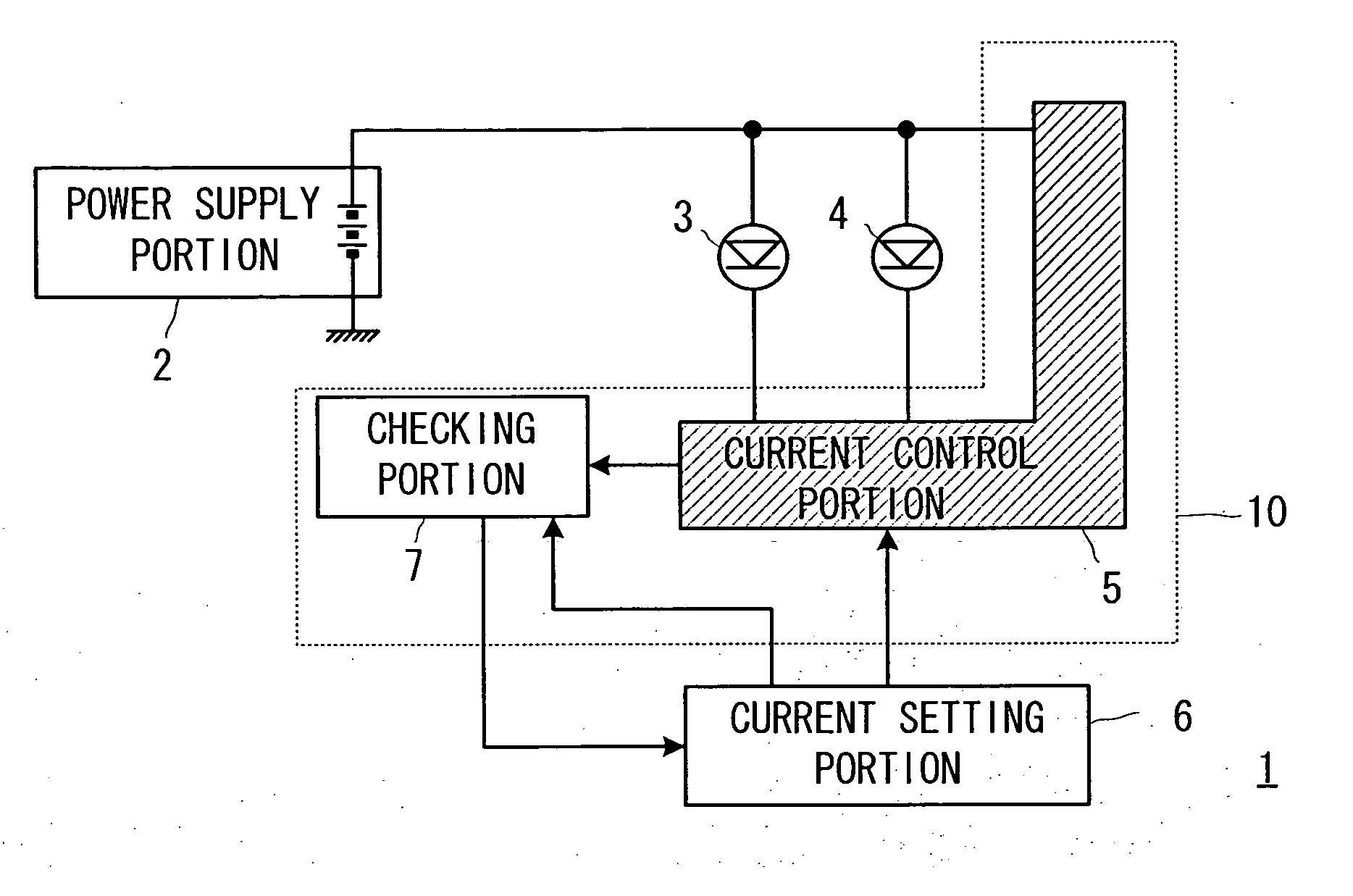
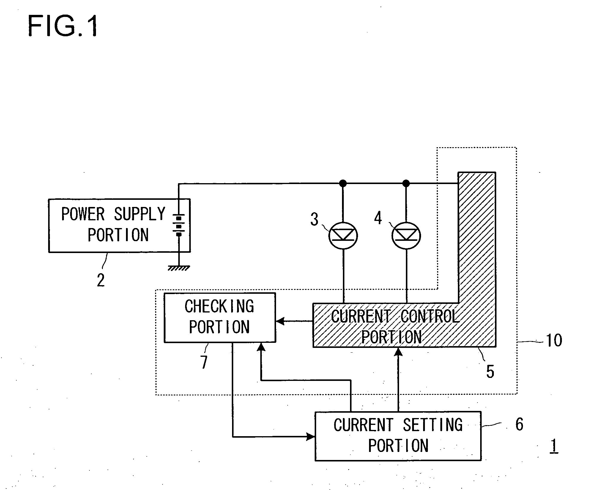
[0038] A first embodiment of the present invention will be described below with reference to the drawings. FIG. 1 is a diagram showing the configuration of part of a liquid crystal display provided with a power supply circuit according to the present invention.

[0039] The liquid crystal display 1 shown in FIG. 1 is composed of a power supply portion 2 that supplies a direct-current voltage; LEDs 3 and 4 that, when current is passed therethrough, emit light of predetermined colors at light intensities commensurate with the amounts of current passed therethrough; a current control portion 5 that controls the current levels of the currents passing between the anode and the cathode of the individual LEDs 3 and 4; a current setting portion 6 that sets the current level of currents to be passed through the LEDs 3 and 4 and gives the current control portion 5 instructions corresponding thereto; and a checking portion 7 that checks whether or not currents at the current level set by the cur...

second embodiment

[0087] A second embodiment of the present invention will be described below with reference to the drawings. Such parts as are found also in the first embodiment are identified with common reference numerals, and no detailed description thereof will be repeated.

[0088]FIG. 7 is a diagram showing the configuration of part of a liquid crystal display provided with a power supply circuit of this embodiment. In this embodiment, as compared with the first embodiment, there are additionally provided a current setting portion 11 separate from the current setting portion 6; a current control portion 12 that performs control such that a current at the current level set by the current setting portion 11 is passed; and an LED 13 through which a current at the current level controlled by the current control portion 12 is passed. Although the current setting portions 6 and 11 are shown to be provided within the power supply circuit 10 in FIG. 7, they may instead be provided outside the power supp...


PUM


Abstract

A power supply circuit (10) has a current control portion (5) that controls, at a predetermined level, the currents passed through LEDs (3) and (4); a current setting portion (6) that sets, in the current control portion (5), the level of currents to be passed through the LEDs (3) and (4); and a checking portion (7) that checks whether or not currents at the current level set by the current setting portion (6) can be passed through the LEDs (3) and (4). The checking portion (7), on recognizing a condition in which at least one of the LEDs (3) and (4) cannot be fed with a current at the level set by the current setting portion (6), feeds the current setting portion (6) with a signal indicating the condition; on receiving the signal, the current setting portion (6) changes the currently set current level to a current level at which currents can be passed through both the LEDs (3) and (4). This helps realize an LED driving power supply circuit that, despite having a small circuit scale, tolerates a wide range for the supplied voltage.

Description

[0001] This nonprovisional application claims priority under 35 U.S.C. § 119(a) on Patent Application No. 2005-243055 filed in Japan on Aug. 24, 2005, the entire contents of which are hereby incorporated by reference. BACKGROUND OF THE INVENTION [0002] 1. Field of the Invention [0003] The present invention relates to a power supply circuit, and more particularly to a driving power supply circuit that is provided for the purpose of stably driving an LED. [0004] 2. Description of Related Art [0005] Today, cellular phones incorporating color liquid crystal displays are widespread. Typically used as the backlights for such liquid crystal displays are white LEDs, and there have conventionally been known power supply circuits for driving such LEDs (for example, see JP-A-2004-166342). [0006]FIG. 8 is a diagram showing the configuration of part of a liquid crystal display provided with the just-mentioned power supply circuit based on conventional technology. The liquid crystal display 900 i...

Claims


Application Information

Patent Timeline
Patent Type & Authority Applications(United States)
IPC IPC(8): G09G5/00H01L33/00H05B37/02
CPCH05B33/0827H05B45/46
Inventor SATOH, TSUTOMU
Owner SHARP KK
Why Eureka
Try Eureka