Ink-jet head

A technology of inkjet head and spray head, which is applied in the direction of inking device and printing, etc., and can solve the problems of uneven ejection liquid volume, lower printing quality, retention of air bubbles or impurities, etc.

Inactive Publication Date: 2008-07-02
TOSHIBA TEC KK
View PDF1 Cites 14 Cited by
  • Summary
  • Abstract
  • Description
  • Claims
  • Application Information

AI Technical Summary

Problems solved by technology

[0004] However, in the above-mentioned inkjet head, the ink does not circulate in the micro-slits and the ink pressure chamber.
Therefore, it is possible to cause air bubbles or impurities to be trapped in micro-slits or pressure chambers
In addition, if ink is continuously and repeatedly ejected from a certain nozzle, the temperature of the ink in the micro-slit may rise.
Therefore, the ejection liquid amount of the ink becomes uneven, and there is a possibility that the printing quality may be lowered.

Method used


Image

  • Ink-jet head
  • Ink-jet head
  • Ink-jet head

Examples


Embodiment Construction

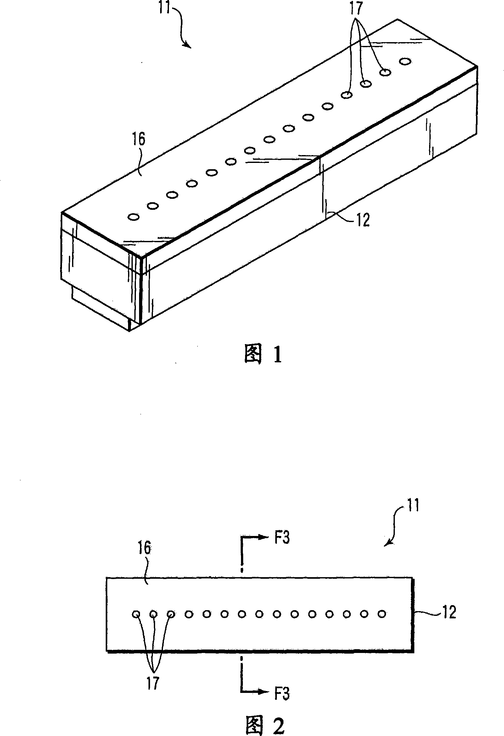
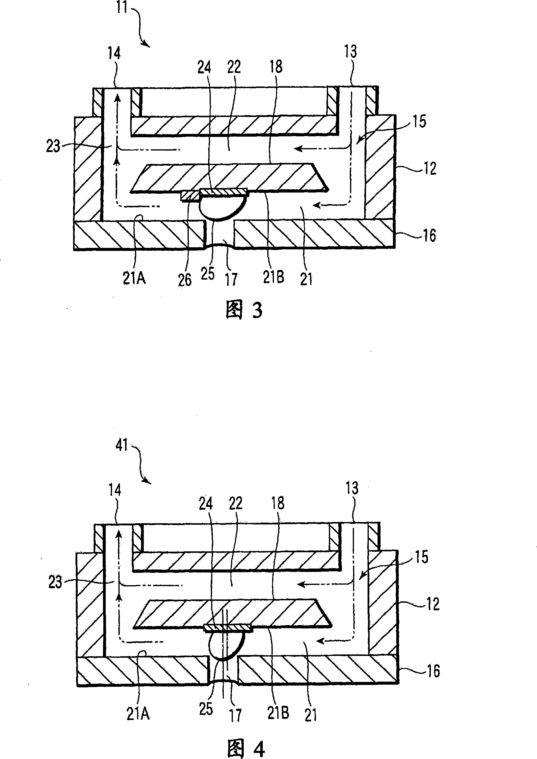
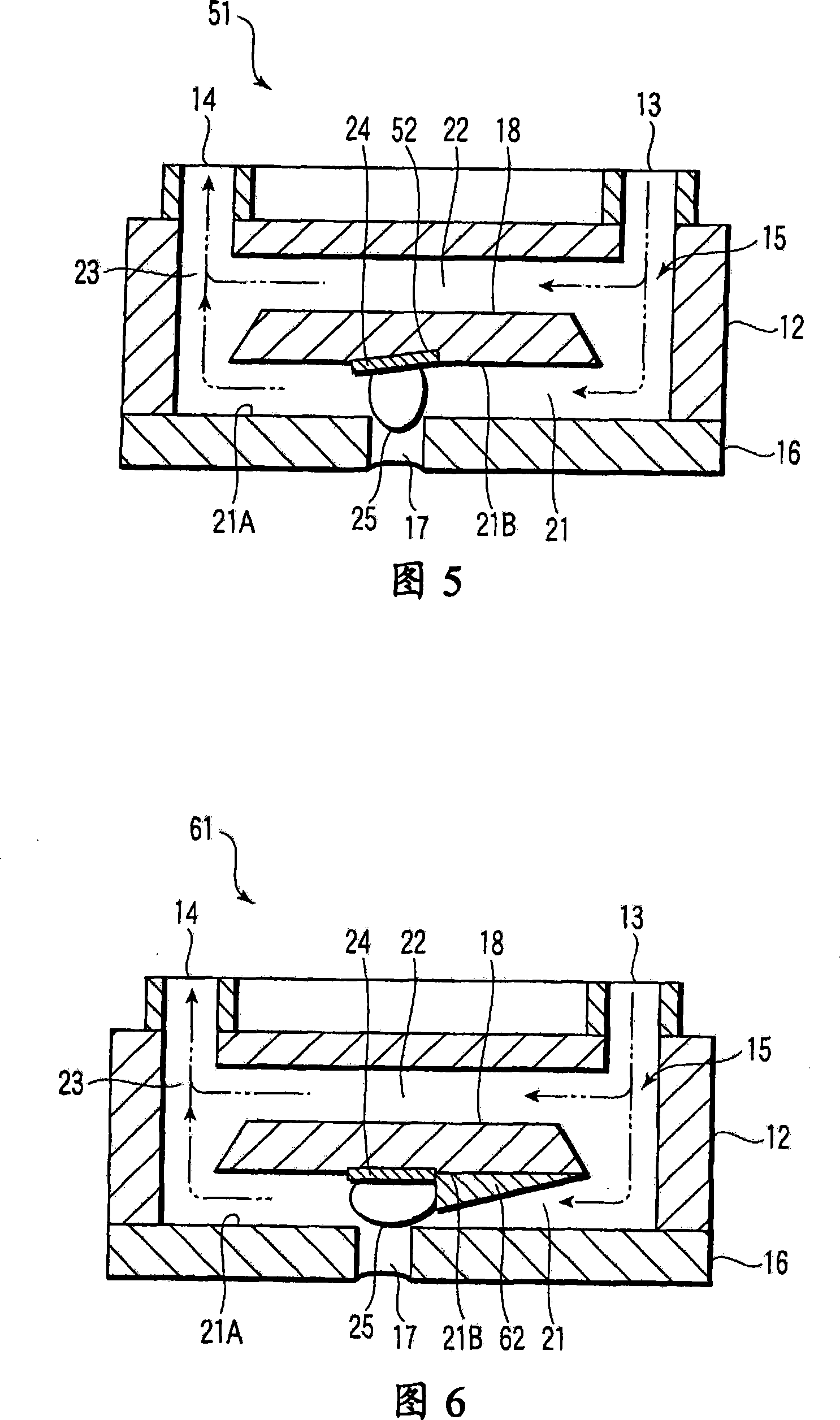
[0015] Next, a first embodiment of the inkjet head will be described with reference to FIGS. 1 to 3 . The inkjet head is mounted on an inkjet recording device, and ejects ink droplets onto a recording medium such as a sheet to form characters, graphics, symbols, and images. The inkjet head is constituted by a so-called ink circulation type head. Hereinafter, the upstream direction refers to the direction toward the inlet, and the downstream direction refers to the direction toward the outlet.

[0016] As shown in Fig. 1, Fig. 2 and Fig. 3, the inkjet head 11 includes: a nozzle body 12; an inflow port 13, which is arranged on the nozzle body 12; an outflow port 14, which is arranged on the nozzle body 12; And an ink flow path 15 formed inside the head main body 12 so as to connect the inflow port 13 and the outflow port 14 . The head body 12 is formed in a square shape. The head body 12 has a nozzle plate 16 on which a plurality of nozzles 17 are formed. The head main body ...


PUM


Abstract

The inkjet head of the present invention includes a head body, an inflow port, an outflow port, an ink flow path, a nozzle, a heater, and a guide portion. The ink flow path is provided inside the head body so as to connect the inflow port and the outflow port. The ink flows through the inside of the ink flow path from the inflow port toward the outflow port. The nozzles are formed on the sides of the ink flow path. The heater is provided in the ink flow path. The heater generates bubble pressure in the ink flow path and ejects ink from the nozzles. The bubble guide structure is provided in the ink flow path, and guides the pressure of the bubble to the nozzle. In addition, the heater may be provided eccentrically with respect to the nozzle, or the heater may be provided obliquely.

Description

technical field [0001] The present invention relates to an inkjet head that ejects ink (ink) toward a medium. Background technique [0002] For example, Japanese Patent Application Laid-Open No. 2005-161633 describes an ink circulation type inkjet head. This inkjet head applies heat to the liquid and generates bubble pressure at the time of foaming generated by the phase change of the liquid, thereby ejecting the liquid. The inkjet head has a substrate having a plurality of nozzles arranged in an array and heaters for ejecting ink from the nozzles. In addition, the inkjet head has an ink reservoir along the arrangement of the nozzles. The inkjet head has a supply channel for supplying ink to the ink storage, and microslits for connecting the nozzles and the ink storage. The supply flow path communicates with the ink storage portion, and the distances from the communication portion to the respective nozzles are formed to be approximately equal. [0003] In this inkjet hea...

Claims


Application Information

Patent Timeline
Patent Type & Authority Applications(China)
IPC IPC(8): B41J2/14
CPCB41J2/1404B41J2202/11B41J2202/12
Inventor 江藤义郎
Owner TOSHIBA TEC KK
Why Eureka
Try Eureka