Combine harvester

A combine harvester and machine body technology, which is applied to harvesters, cutters, agricultural machinery, etc., can solve the problems of reduced cutting performance of harvesting devices, slippage of transmission belts, and higher costs, so as to achieve efficient harvesting operations, realize the number of parts, The effect of cost reduction

Active Publication Date: 2012-02-22
KUBOTA LTD
View PDF5 Cites 13 Cited by
  • Summary
  • Abstract
  • Description
  • Claims
  • Application Information

AI Technical Summary

Problems solved by technology

[0004] In the above conventional structure, the belt transmission mechanism that interlocks the intermediate shaft and the harvesting knife drive box is arranged on the lateral outer side of the harvesting section, so a large number of components are required in the harvesting device drive system, resulting in high cost.
In addition, due to the friction transmission through the transmission belt, there may be transmission slippage caused by wear or elongation of the transmission belt, which will reduce the cutting performance of the harvesting device, so the maintenance of the transmission belt must be fully carried out.

Method used


Image

  • Combine harvester
  • Combine harvester
  • Combine harvester

Examples


Embodiment Construction

[0073] (summary of combine harvester)

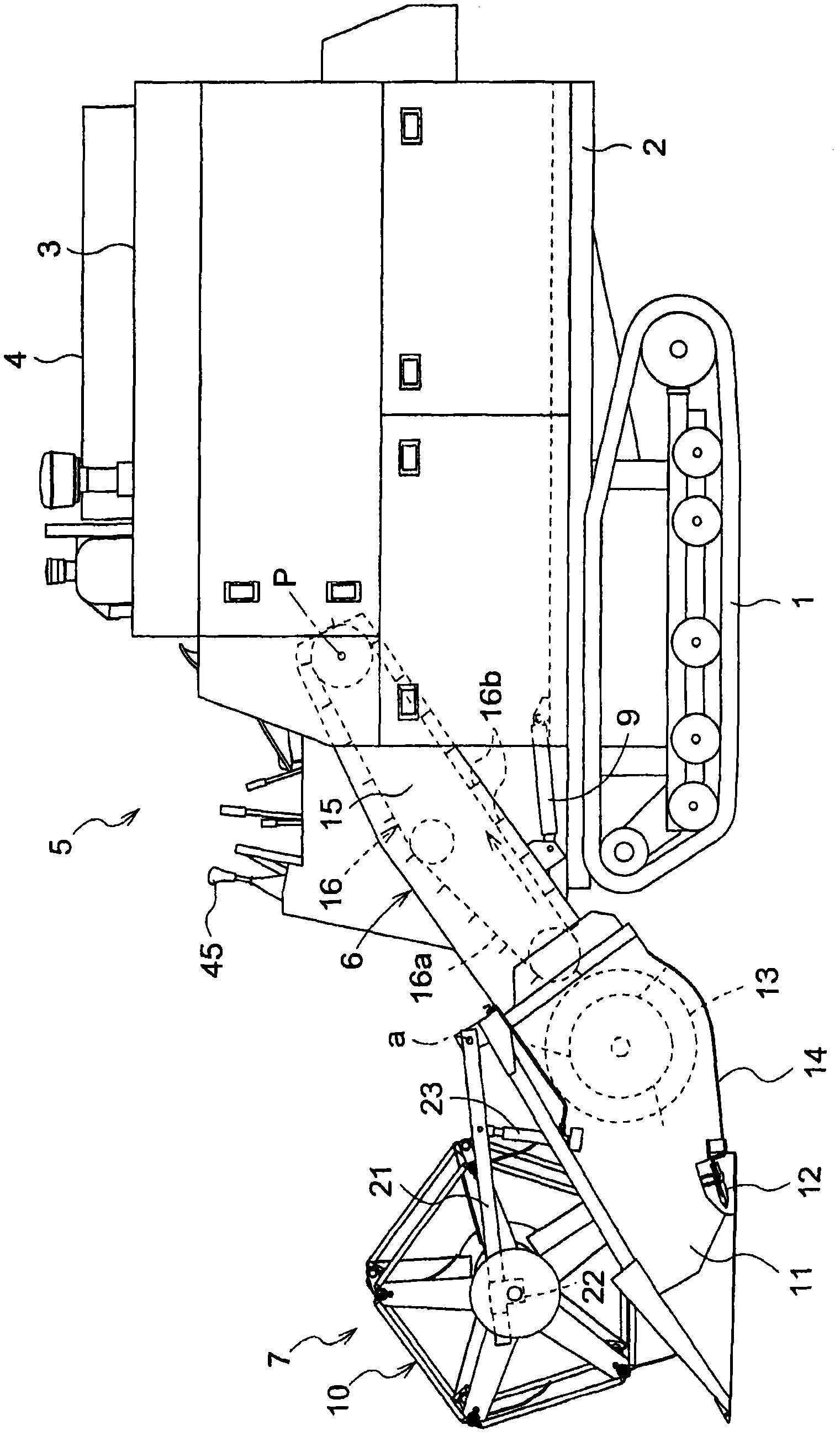
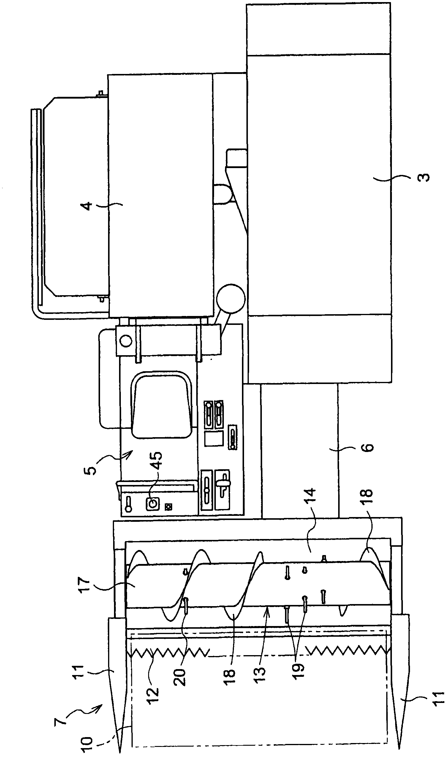
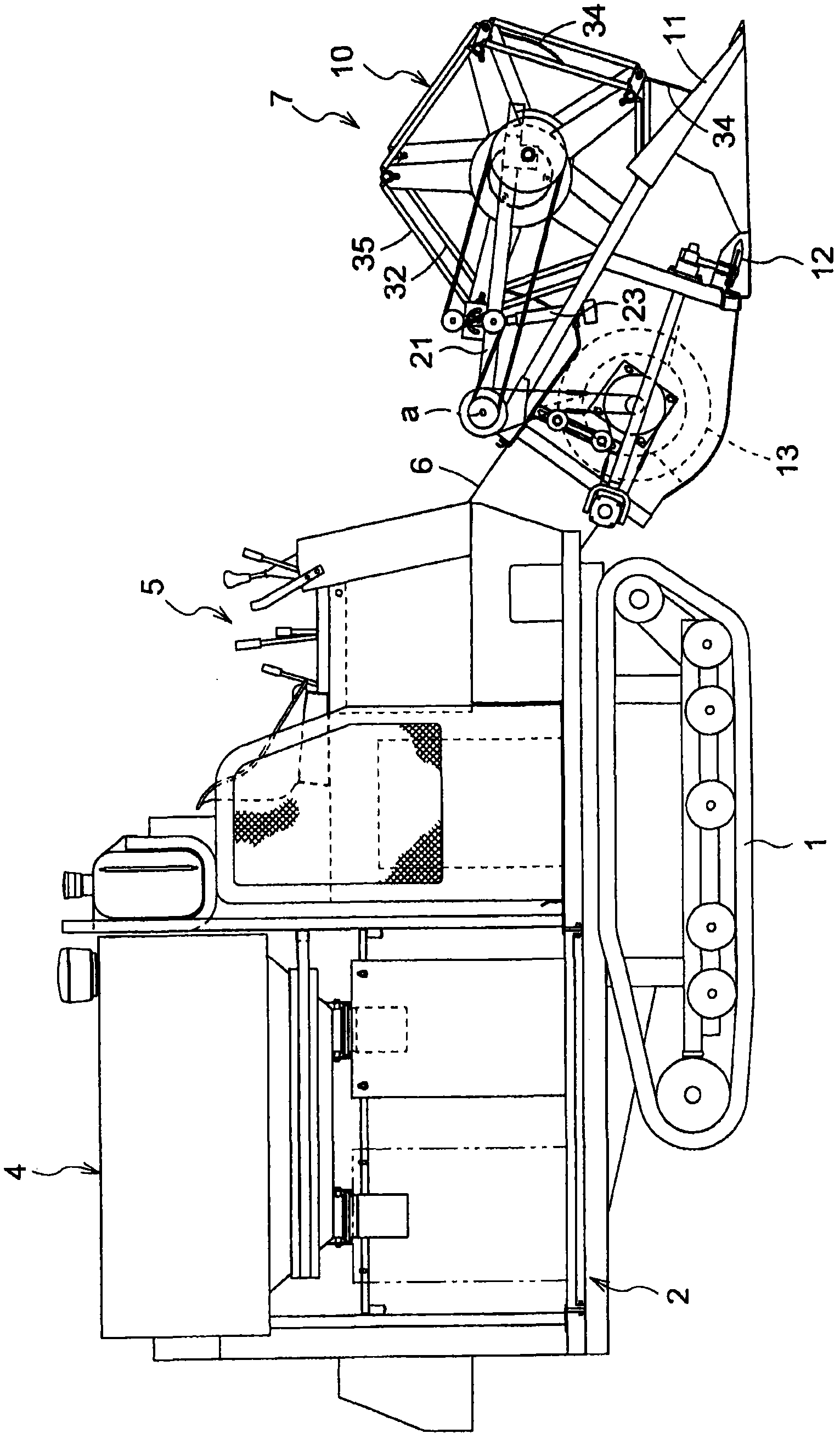
[0074] figure 1 shows the overall side of the common type combine harvester of the present invention, figure 2 Its overall top surface is shown. This combine harvester is equipped with an axial flow type threshing device 3 and a bagging type grain recovery part 4 side by side on the traveling body 2 equipped with a pair of left and right crawler belt traveling devices 1, and the grain recovery part 4 The front of is equipped with driving part 5. In the front part of the threshing device 3, a feeder 6 for conveying harvested straw is connected in a manner to swing freely around the fulcrum P up and down, and a feeder 6 having a harvesting width approximately equivalent to the lateral width of the machine body is connected to the front end of the feeder 6 . The harvesting section 7 is equipped with an engine 8 laterally below the driving section 5 .

[0075] A hydraulic cylinder 9 is erected between the front part of the traveling bod...


PUM


Abstract

The invention provides a combine harvester. The combine harvest can simplify drive systems of harvesting devices. And by using the combine harvester, the harvesting devices can be driven reliably without any special maintaining work. A rotation converting mechanism (70) is arranged on a middle shaft (65) to convert a rotation of the middle shaft (65) around a transverse axis to a reciprocate rotation around a longitudinal axis. And a transmission shaft (74) transmitting rotation power of the reciprocate rotation after the conversion extends forward. A front end part of the transmission shaft (74) connects with a harvesting device (12) in linkage.

Description

[0001] This application is a divisional application of an invention patent application with the title of the invention "Combine Harvester", the filing date being September 11, 2006, and the application number being 200610151518.0. technical field [0002] This invention relates to the combine harvester provided with the harvesting part provided with the clipper type harvesting device, the screw conveyor for horizontal feed, and the rake drum at the front end of the feeder connected to the front part of a threshing apparatus. Background technique [0003] As a reaping part drive structure in the said combine, the structure disclosed, for example in Unexamined-Japanese-Patent No. 2005-211010 is known. That is, the power output from the intermediate shaft on the back of the harvesting section from the horizontal frame is transmitted to the harvesting knife drive box near the lateral side of the harvesting device via the transmission belt, and the harvesting knife drive box and t...

Claims


Application Information

Patent Timeline
Patent Type & Authority Applications(China)
IPC IPC(8): A01D41/00A01D69/06A01D57/00A01B71/00
Inventor 濑川卓二深井宏南龙一西辉雄
Owner KUBOTA LTD
Why Eureka
Try Eureka