Entrance safety device for passenger conveyer
A technology for passenger conveyors and safety devices, which is used in transportation and packaging, escalators, etc., can solve the problems of occupying space, obstruction of multiple groups of components, and difficulty in installing information display devices, and achieve the effect of ensuring safety.
- Summary
- Abstract
- Description
- Claims
- Application Information
AI Technical Summary
Problems solved by technology
Method used
Image

Examples
no. 1 example
[0038] 4 to 10 show a first embodiment in which the entrance safety device of a passenger conveyor according to the present invention is applicable.
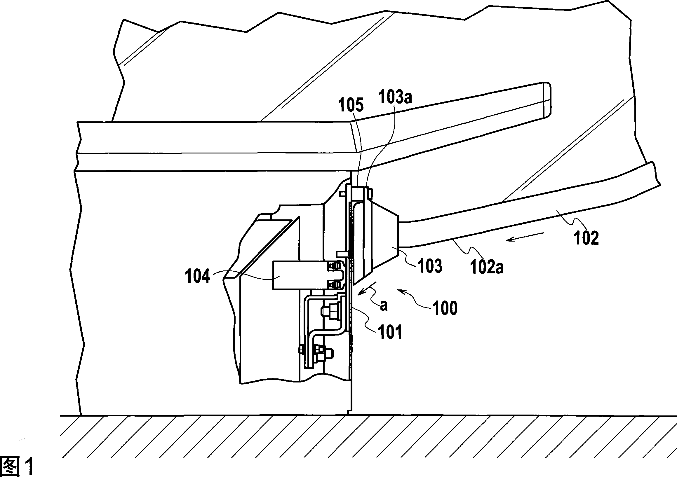
[0039] As shown in Figure 4, the escalator 1 as a kind of passenger conveyor comprises: the truss structure 2 arranged between the upper floor and the lower floor; Steps 3 are connected one after another to form an endless loop; paired railings 4 are vertically arranged on both sides of each step of the plurality of steps 3; pairs of moving handrails 5 are continuously circulated, and the moving handrails 5 are attached to the sides of the railings 4 on the periphery and move synchronously with the steps 3; and a pair of skirts 6 arranged between one passenger platform on the upper floor and another passenger platform on the lower floor for covering the lower positions of the paired railings.
[0040] When the escalator 1 runs along the rising direction U, the moving handrail 5 exits from the skirt 6 near the lower passenger pla...
no. 2 example
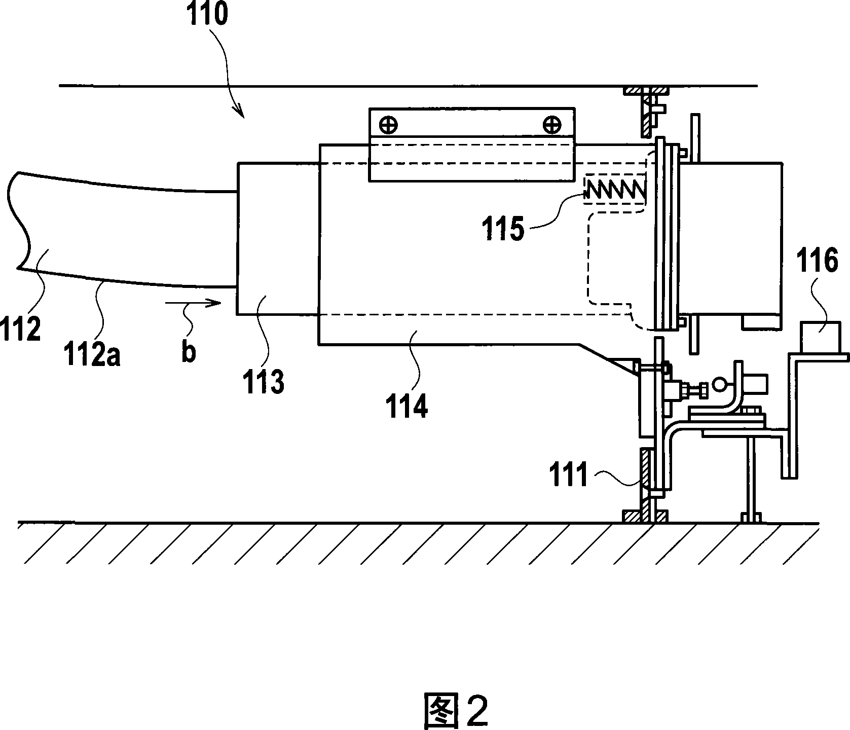
[0054] 11 to 14 show an access safety device according to a second embodiment of the present invention.
[0055] The entrance safety device 20 according to the second embodiment includes: an entrance part 21 , an entrance support part 22 , a fixing part 23 , two pairs of connection parts 24 , a pulling spring 25 and a safety switch 26 . The inlet member 21 fits in the rail / handrail hole 7 on the front panel 6c with only its top end protruding (approximately 5mm) from the protrusion 6d on the front panel 6c. The inlet support member 22 is fixed to the rear end portion of the inlet member 21 . The fixing member 23 is fixed to the escalator main body (conveyor main body). The connection members 24 are configured as inlet movement guides for connecting the inlet support members 22 to the fixed members 23, respectively. The tension spring 25 serves as biasing means for biasing the inlet part 21 in a direction opposite to the moving direction h of the moving armrest 5 . The safet...
no. 3 example
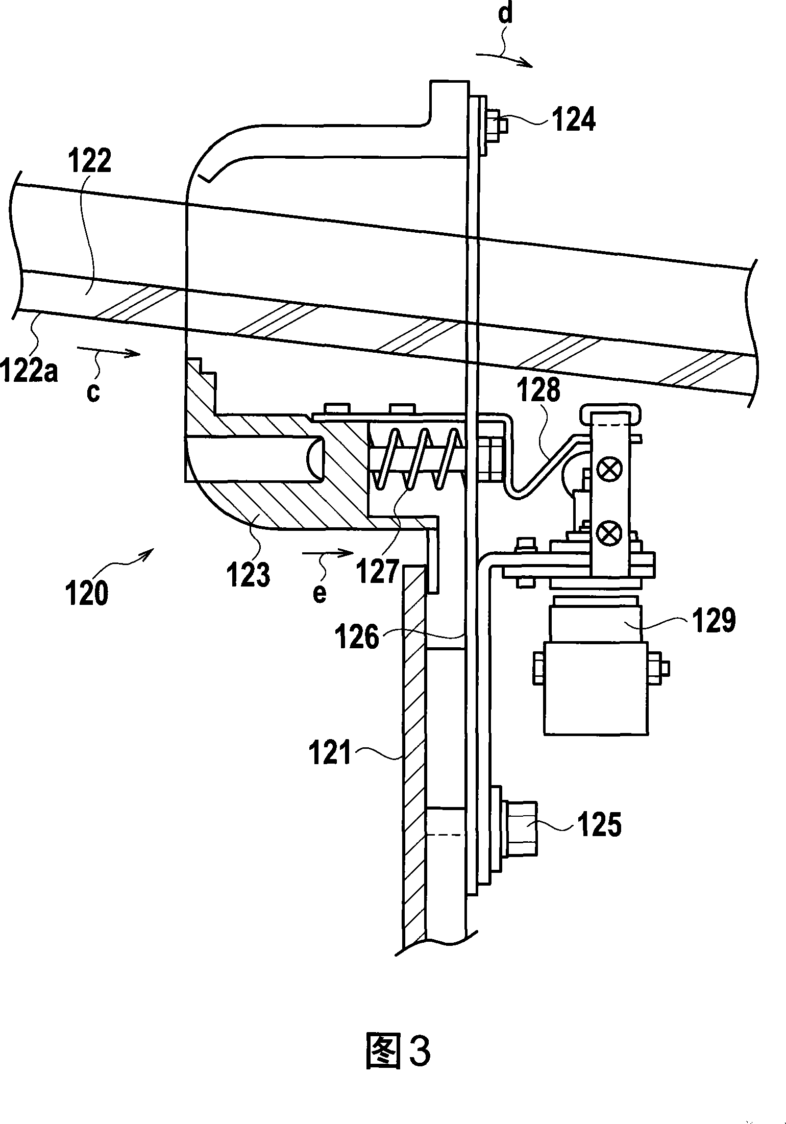
[0068] 15 and 16 show a third embodiment of the present invention.
[0069] Similar to the entrance safety device 20 according to the second embodiment, the entrance safety device 30 according to the third embodiment includes: an entrance part 31, an entrance support part 32, a fixing part 33, two pairs of connection parts 34, a tension spring 35 and a safety switch 36. The inlet part 31 fits in the rail / handrail hole 7 on the front panel 6c with only its top end protruding (approximately 5 mm) from the protrusion 6d on the front panel 6c. An inlet support member 32 is fixed to a rear end portion of the inlet member 31 . The fixing member 33 is fixed to the escalator main body (conveyor main body). The connecting members 34 are configured as inlet movement guides for connecting the inlet supporting members 32 to the fixing members 33 , respectively. The tension spring 35 serves as biasing means for biasing the inlet part 31 in a direction opposite to the moving direction h ...
PUM
 Abstract
Description
Claims
Application Information
PatSnap Eureka turns technology decisions into work you can execute. Powered by our Innovation Knowledge Graph, it runs expert workflows across engineering, life sciences, materials and intellectual property. Get your review-ready output in minutes.


