
Cam mechanism, loom and method for decoupling the cams from the cam mechanism roller

A cam mechanism and cam technology, which are applied in the cam opening mechanism, textile, textile and papermaking, etc., can solve the problems of unprovable leveling device and complex shape.

Active Publication Date: 2008-07-16
STAUBLI FAVERGES SA
View PDF1 Cites 6 Cited by
  • Summary
  • Abstract
  • Description
  • Claims
  • Application Information

AI Technical Summary

Problems solved by technology

The reliability of this leveling device requires the production of high precision and robust components with complex shapes
In some applications, however, the frequency of maintenance does not justify the installation of such complex and expensive leveling devices

Method used


Image

  • Cam mechanism, loom and method for decoupling the cams from the cam mechanism roller
  • Cam mechanism, loom and method for decoupling the cams from the cam mechanism roller
  • Cam mechanism, loom and method for decoupling the cams from the cam mechanism roller

Examples


Embodiment Construction

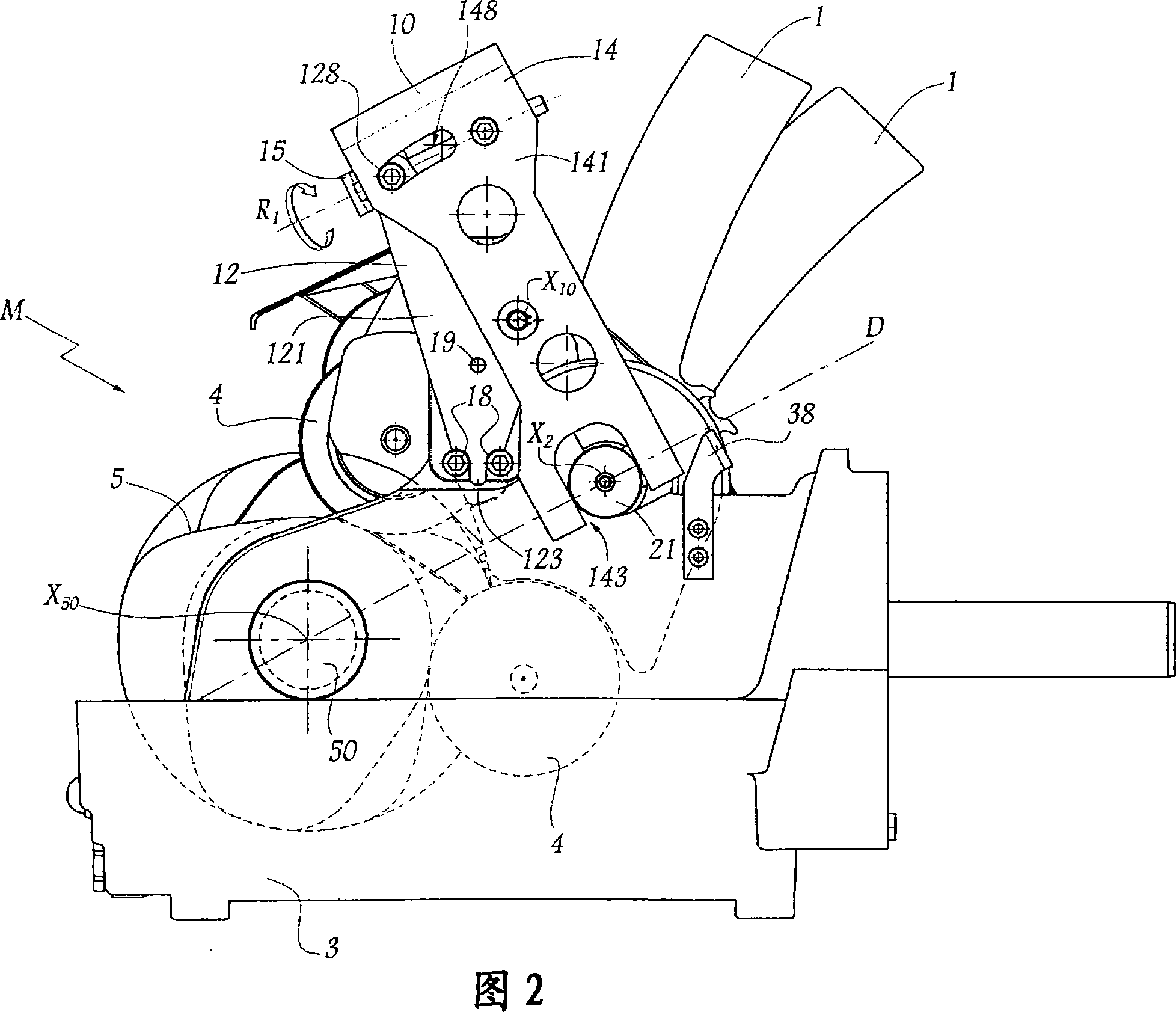
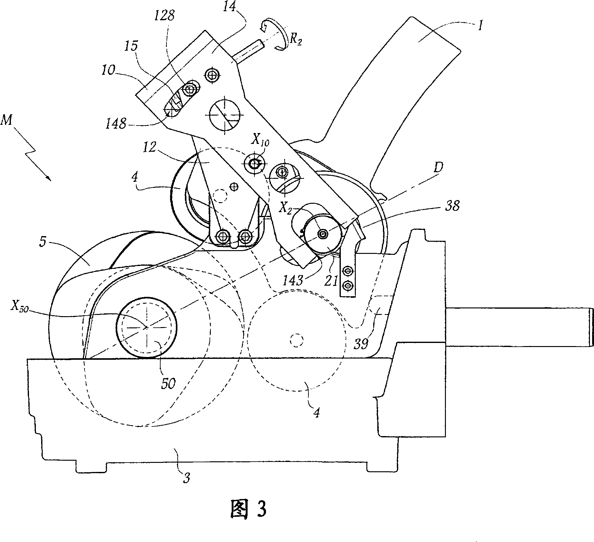
[0025] In the present invention, "non-leveling configuration" or "operating configuration" of a cam mechanism refers to the configuration of the mechanism when the loom on which the mechanism is installed is in the operating configuration. Likewise, a "leveled configuration" of a cam mechanism refers to a mechanism configuration in which the cam is separated from the rollers of the oscillating lever—in other words, the contact between the cam and the rollers is loosened.

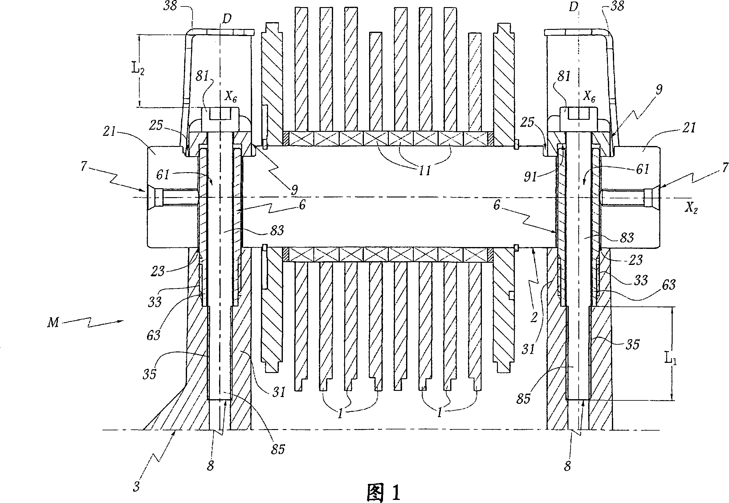
[0026] The cam mechanism M shown in Figures 1-3 is used in a loom (not shown) comprising a plurality of heald frames whose alternating vertical movement is controlled by the mechanism M.

[0027] The mechanism M comprises a plurality of oscillating rods 1, one for each heald frame of the loom, all mounted about the longitudinal axis X 2 The common non-rotating shaft 2 pivots, which is supported by the supporting structure 3 of the mechanism. The rotational guidance of the pivot lever 1 about the shaft 2 is ...


PUM


Abstract

The invention provides a cam mechanism, a loom and a method for decoupling the cams in relation to the cam followers of a cam mechanism. The cam mechanism for forming a shed on the loom comprising swing levers for driving a heald frame, wherein the swing levers are pivoting fixed on a same shaft and disposed with followers moving according to the cam of the mechanism. The shaft acts a translational motion along the back direction of the followers from the radial of the cam relatively to the the support structure of the mechanism, to decouple the cam and the followers. Therefor, The mechanism comprises at least a post for guide the shaft to translate along the back direction, wherein the post is fixed relatively to the support structure of the mechanism and is contained in a bearer of the shaft, and the bearer extends in a transverse direction relatively to a direct axis of the shaft.

Description

technical field [0001] The present invention relates to a cam mechanism for shedding on a loom, a loom and a method for separating the cam from the roller of the cam mechanism. Background technique [0002] In a loom, the cam mechanism usually includes a plurality of swing rods supported by a common shaft, and the number of the swing rods is equal to the number of heald frames fitted with the mechanism on the loom. Each oscillating lever is hooked on a heald frame and has two rollers that follow the trajectory of a complementary cam that rotates about an axis common to all the cams of the mechanism. Rotation of the cams, which are appropriately offset from each other at angular intervals about the camshaft, operates the swing lever and moves the heald frames up and down. [0003] For certain maintenance or adjustment operations on the loom, the cam must be separated from the rollers of the cam mechanism and / or all loom heald frames must be level with each other. Leveling r...

Claims


Application Information

Patent Timeline
IPC IPC(8): D03C5/00D03C9/06
CPCD03C5/02D03C5/005
Inventor B·塔迪J-P·帕热斯
Owner STAUBLI FAVERGES SA
Learn More