
Transceiver module for optical communications and method for transmitting and receiving data

A connector module, multi-fiber technology, applied in the field of optical communication, can solve the problem that the requirements of wiring and rewiring can not be met, etc.

Active Publication Date: 2008-07-16
AVAGO TECH INT SALES PTE LTD
View PDF2 Cites 18 Cited by
  • Summary
  • Abstract
  • Description
  • Claims
  • Application Information

AI Technical Summary

Problems solved by technology

As a result, wiring and rewiring requirements cannot be met, or can be done with considerable difficulty and cost

Method used


Image

  • Transceiver module for optical communications and method for transmitting and receiving data
  • Transceiver module for optical communications and method for transmitting and receiving data
  • Transceiver module for optical communications and method for transmitting and receiving data

Examples


Embodiment Construction

[0027]One of the connector modules described herein is designed and shaped to mate with one side (e.g., the rear side) of the board's receptacle, and one of the connector modules described herein is designed and shaped to mate with the other side (e.g., the rear side) of the board's receptacle. For example, front side) matches. The two connector modules have features that make them extremely precise in physical and optical alignment and, at the same time, can be manufactured at relatively low cost. Connector modules designed and shaped to mate with one side of the receptacle of the board have mating means that enable them to be stacked one on top of the other inside the receptacle in a relatively rigid stack. Connector modules designed and shaped to mate with the other side of the board's receptacle have mating means that enable them to be held in slots slightly separated from each other by an air gap so that the connector modules "float" in the receptacle. By relatively rigi...


PUM


Abstract

Connector modules designed and shaped to mate with the receptacle side of the board have mating means that enable them to be stacked one upon the other within the receptacle in a relatively rigid stack. Connector modules designed and shaped to mate with the other side of the board's receptacle have mating means that enable them to be held in slots slightly separated from each other by an air gap to allow them to "float" in the receptacle. By floating the connector modules on one side of the receptacle and stacking them relatively rigidly on the other side of the receptacle, it is ensured that a very precise optical alignment is maintained between the respective lenses of the connector modules facing each other in the receptacle.

Description

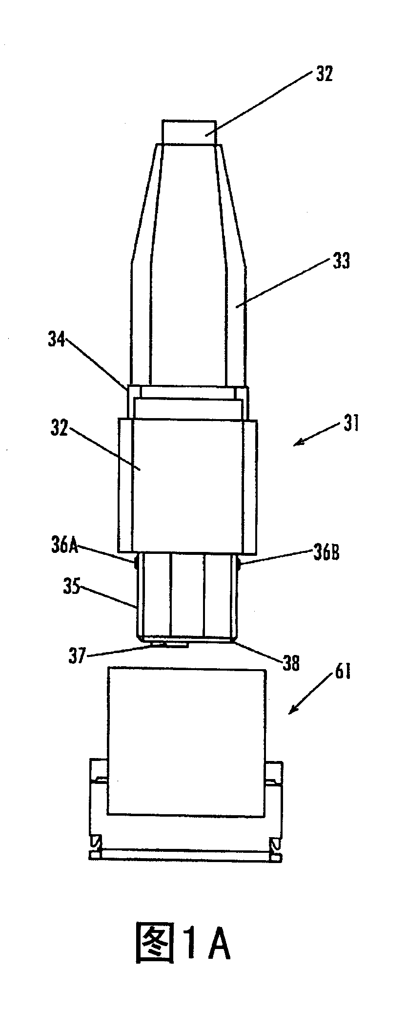
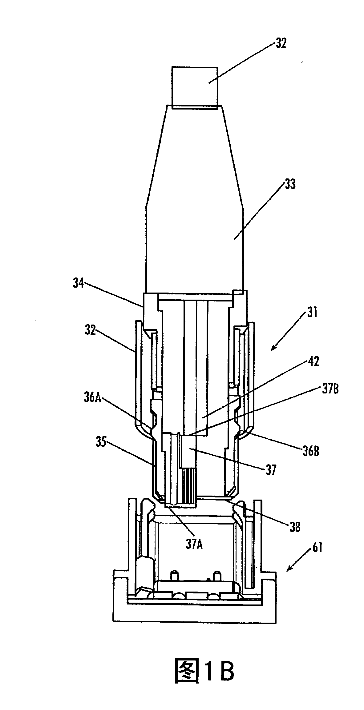
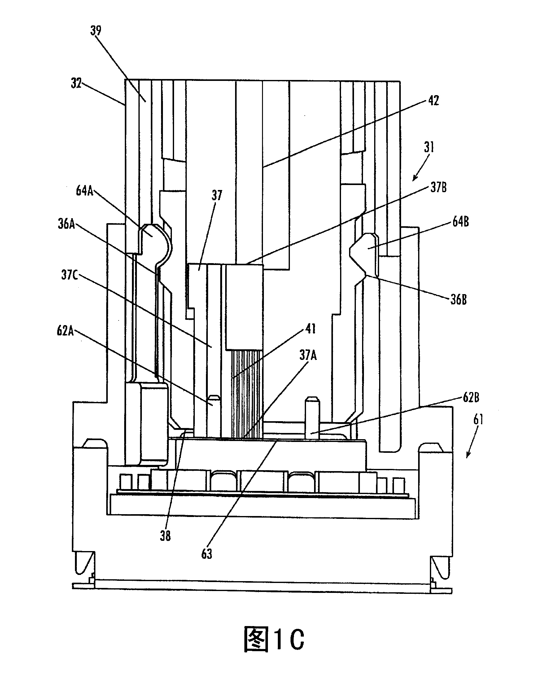
technical field [0001] The present invention relates to optical communications. More particularly, the present invention relates to stackable multi-fiber connector modules and receptacles and plugs configured to receive and align stacks of stackable multi-fiber connector modules. Background technique [0002] In optical communication networks, various types of devices are used to couple light from one end of an optical fiber into another end of an optical fiber to an optical sensor (e.g., a photodiode) in a transceiver module and couple light from the light emitting device (eg, laser diode) of the transceiver module into the end of the optical fiber. [0003] Figure 1A illustrates a perspective view of a known multi-fiber connector module 31 manufactured by US Conec Ltd. of Hickory, N.C. Connector module 31 has been known in the optical connector industry as MTP  Connector. Connector module 31 holds the end of the receiving optical fiber and has an optical system that i...

Claims


Application Information

Patent Timeline
IPC IPC(8): G02B6/38G02B6/36
Inventor 劳伦斯·雷·麦克洛克
Owner AVAGO TECH INT SALES PTE LTD
Learn More