Discharge hopper and method of discharing trays filled with rod-shaped articles

A technology for unloading hoppers and brackets, which is applied in the field of unloading hoppers and unloading brackets with rod-shaped products, which can solve the problems of uneven unloading operations, etc.

Inactive Publication Date: 2008-08-06
HAUNI MASCHINENBAU AG
View PDF0 Cites 8 Cited by
  • Summary
  • Abstract
  • Description
  • Claims
  • Application Information

AI Technical Summary

Problems solved by technology

However, this type of equipment has the disadvantage of uneven unloading operation despite the monitoring of the product flow in the unloading hopper

Method used


Image

  • Discharge hopper and method of discharing trays filled with rod-shaped articles
  • Discharge hopper and method of discharing trays filled with rod-shaped articles

Examples


Embodiment Construction

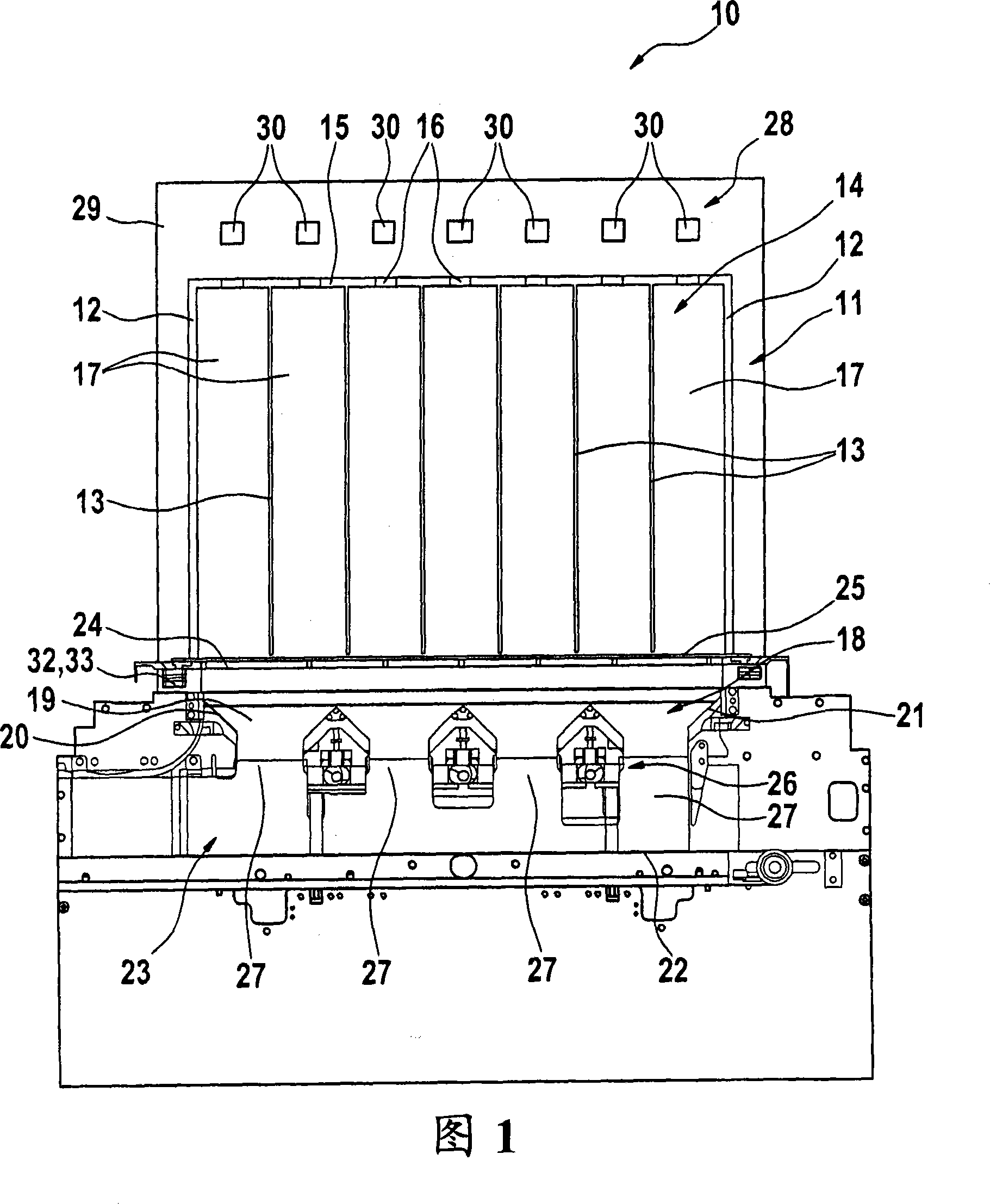
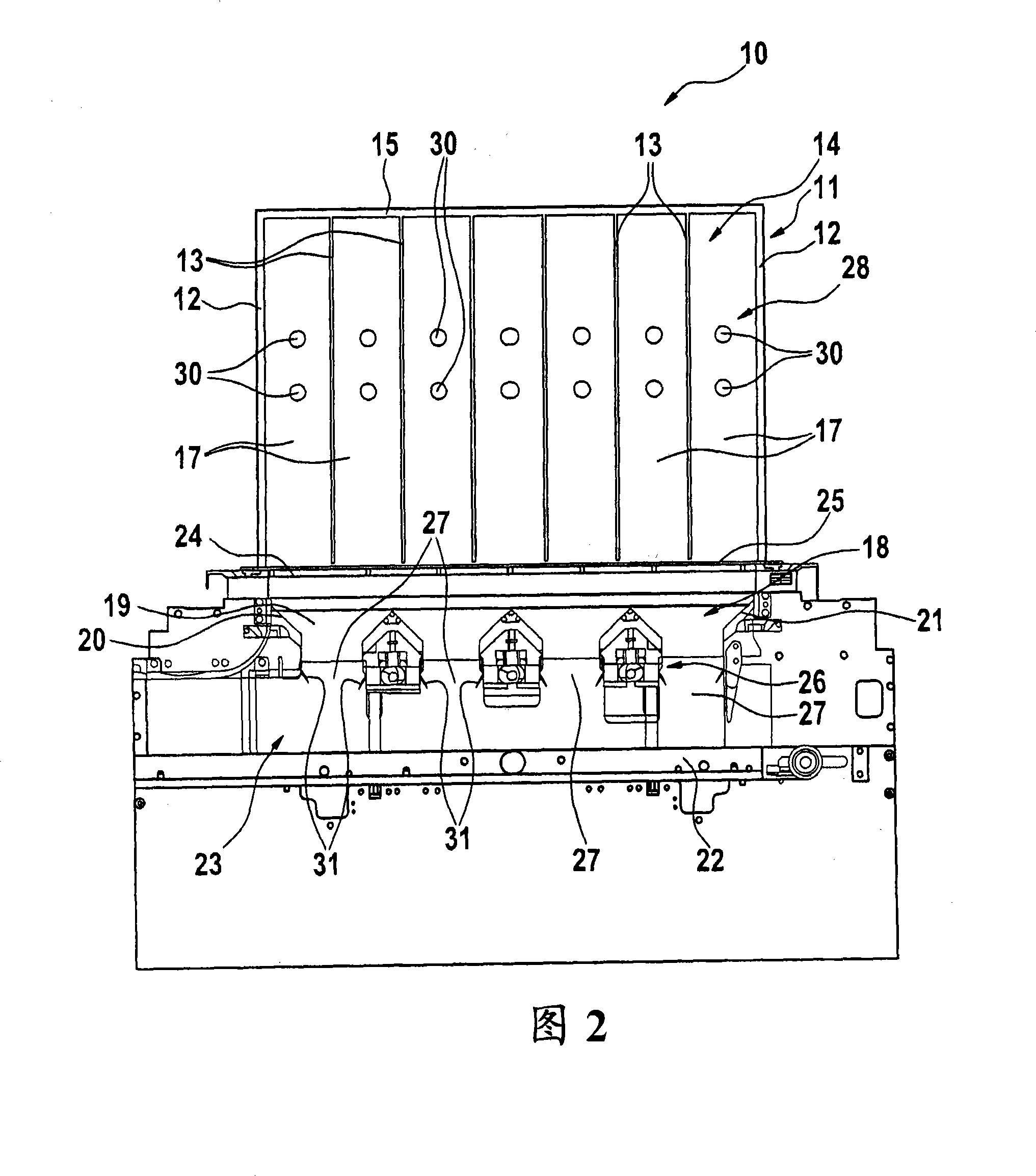
[0015] The unloading hopper is used for unloading the brackets or shaft brackets with rod-shaped products.

[0016] FIG. 1 shows a first embodiment of such a dump hopper 10 designed to unload shaft carriages 11 . The shaft bracket 11 has a side wall 12 , a shaft wall 13 parallel to the side wall 12 , a rear wall 14 and a bottom wall 15 . The bottom wall may have openings 16 (see FIG. 1 ) or be at least translucent to allow monitoring means as described below to detect the level within the wellbore 17 . The same is true for the rear wall 14 . The discharge hopper 10 has a receiving chamber 18 comprising a rear wall 19 , a front wall not shown for better clarity and side walls 20 , 21 . At the bottom, the receiving chamber 18 is delimited by a conveying member 22 which can be driven in both directions and which is arranged at a distance from the receiving chamber 18 so as to form a slot 23 . At the top end, the receiving chamber 18 is open in the direction of the shaft bracke...


PUM


Abstract

The hopper (10) has a receiving chamber (18) for rod-shaped products flowing from a shaft tray (11), where the chamber includes a top, which opens in a direction of the tray and a bottom comprising a conveying element (22) defining a channel (23) for carrying away the products. Flow regulating elements (26) are located within the chamber to control a flow of the products within the hopper. A monitoring unit (28) is arranged and constructed to detect a level of products within the tray, and operatively connected to the regulating elements for individual control of the regulating elements. An independent claim is also included for a method for discharging a tray inserted in a discharge hopper and filled with rod-shaped products.

Description

technical field [0001] The present invention relates to a discharge hopper for a tray unloading station for unloading trays, in particular shaft trays, containing rod-shaped products, comprising a discharge hopper for flow from the tray receiving chamber for the product, which is open at the top in the direction of the carriage and is limited at the bottom by means of conveying parts forming slots for carrying away the product, and flow regulating parts in the receiving chamber for controlling the flow rate during unloading Product flow inside the hopper. Furthermore, the present invention relates to a method for unloading a rack, in particular a shaft rack, filled with rod-shaped products, comprising the steps of: opening the rack or shaft rack, passing the flow of product through the receiving cavity of the discharge hopper to the conveyor In the region of the element, the product flow is regulated by means of flow regulating elements in the receiving chamber and in the reg...

Claims


Application Information

Patent Timeline
Patent Type & Authority Applications(China)
IPC IPC(8): A24C5/352B65B19/04B65D88/54B65G65/40
CPCB65G47/19B65G43/08A24C5/356
Inventor P·巴德尼T·米勒M·霍恩M·克纳比A·迈耶
Owner HAUNI MASCHINENBAU AG
Why Eureka
Try Eureka