
Image processing device and image processing method

An image processing device and image processing technology, applied in the direction of image communication, electrical components, etc., can solve problems such as device performance degradation, complicated setting items, and setting errors

Inactive Publication Date: 2008-08-06
KK TOSHIBA +1
View PDF1 Cites 12 Cited by
  • Summary
  • Abstract
  • Description
  • Claims
  • Application Information

AI Technical Summary

Problems solved by technology

[0003] In the prior art described above, in order to generate a preview image during scanning by the scanner, a large amount of image data, such as image data processing and preview data generation, must be processed at the same time. In order to solve the problem that the performance of the device is degraded, it is necessary to generate a preview image after the scanning process is completed.
[0004] In recent years, due to the advanced processing functions of image processing devices, the setting items have become more complicated, and setting errors have become more likely to occur.
However, in the display timing of the preview image of the above-mentioned conventional image processing apparatus, for example, when copying processing is desired, the printing processing ends while the setting content is confirmed. Prevent processing based on wrong setting content

Method used


Image

  • Image processing device and image processing method
  • Image processing device and image processing method
  • Image processing device and image processing method

Examples


no. 1 example

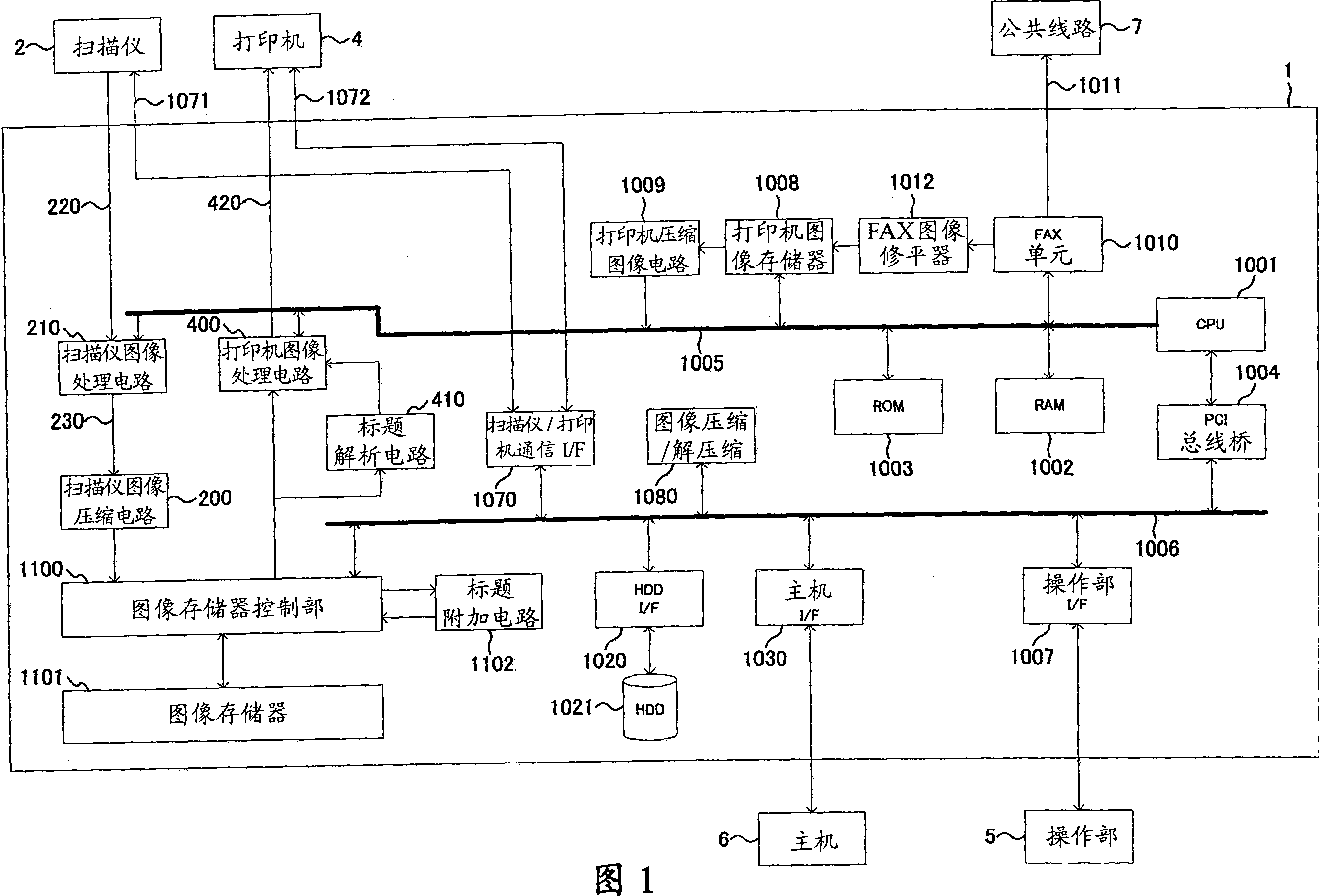
[0029] Fig. 1 is a diagram showing the circuit configuration of an image processing apparatus according to a first embodiment of the present invention. The image processing apparatus of the embodiment of the present invention, for example, constitutes an MFP (Multi Function Peripheral: Multi Function Peripheral).

[0030] As shown in FIG. 1, the image processing apparatus M of this embodiment includes a system control unit 1, a scanner (scanning unit) 2, a printer (printing unit) 4, and an operation display unit 5.

[0031] The system control unit 1 controls the entire system. The system control unit 1 will be described in detail later.

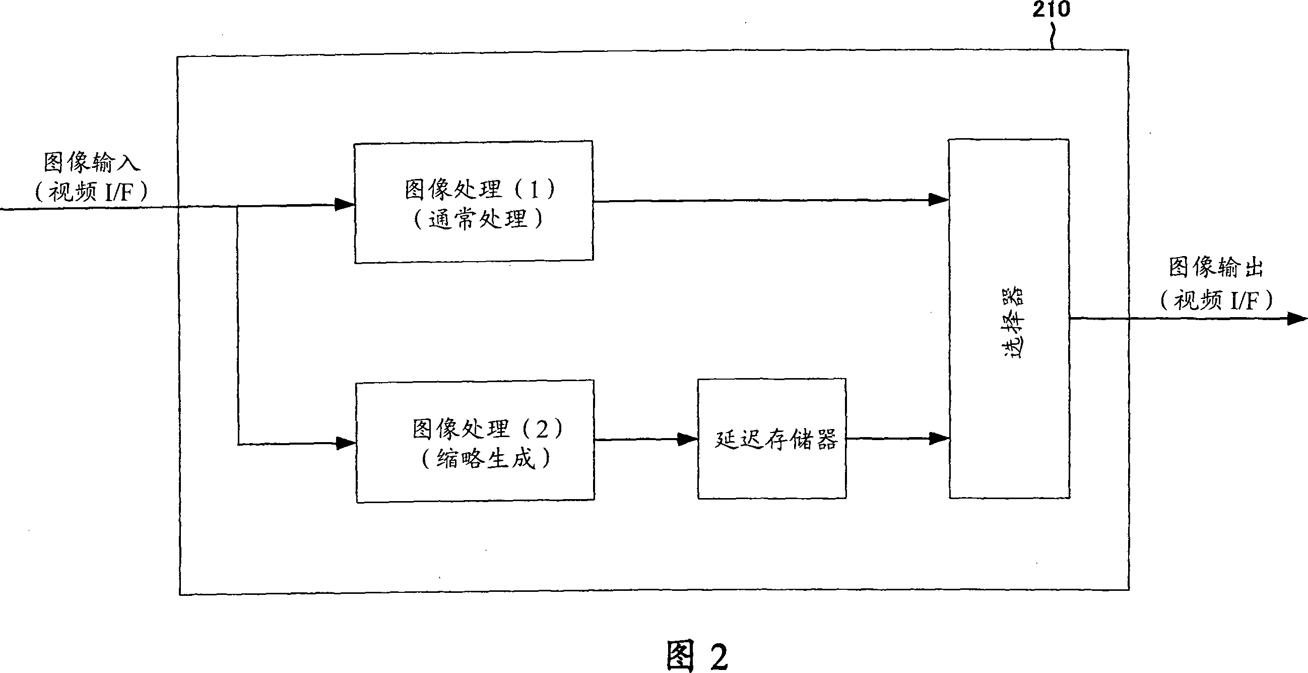
[0032] The scanning unit 2 includes: an image input unit that scans the original while irradiating the original with a light source, and reads the image of the reflected light from the original via a color CCD sensor; and a scanner image processing circuit 210 that performs image reading unit γ correction , Color conversion, main scanning zoom ra...

no. 2 example

[0111] Next, the second embodiment of the present invention will be explained. This embodiment is a modification of the above-mentioned first embodiment, and its basic device structure is the same as that of the first embodiment.

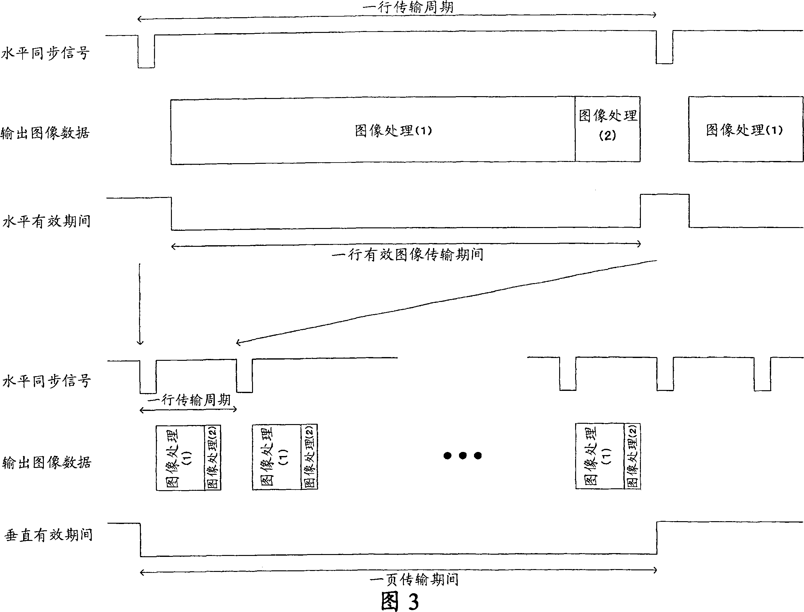
[0112] FIG. 5 is a diagram for explaining an example in which the image processing results of the image processing (1) and the image processing (2) are output in a linked manner in one page cycle. In addition, regarding the image transmission method using the scanner image processing circuit 210, that is, video transmission, the operation is the same as that shown in FIG. 3.

[0113] Hereinafter, the process of linking and outputting the image processing results of the image processing (1) and the image processing (2) in a one-page cycle will be described.

[0114] First, during the vertical valid period of the input image, the processing result of the image processing (1), which is the normal processing, is selected by the selector and output. During t...

no. 3 example

[0120] Next, a third embodiment of the present invention will be explained. This embodiment is a modification of the above-mentioned first embodiment, and its basic device structure is the same as that of the first embodiment.

[0121] FIG. 6 is a diagram for explaining an example in which image processing results of image processing (1) and image processing (2) are output as separate pages. In addition, regarding the image transmission method that uses the scanner image processing circuit, that is, video transmission, the operation is the same as that shown in FIG. 3.

[0122] Hereinafter, a method of outputting the image processing results of the image processing (1) and the image processing (2) as separate pages will be described.

[0123] First, during the vertical valid period of the input image, the normal processing, that is, the processing result of the image processing (1) is selected by the selector and output. During the valid period of the input image, one page of the ...


PUM


Abstract

The invention discloses an image processing device that processes the image data by inhibiting an error-based set content, comprising a set information obtaining unit that obtains a piece of set information regulating processing content as the image data of the processing object; an image processing unit that processes the image data as the processed object based on obtained set information from the set information obtaining unit; an image creation unit that creates an image representing state which processes the image data as the processed object before process of the image processing unit. The process is based on the set information obtained from the set information obtaining unit; a display control unit that displays the image created by the image creation unit; an output indicating receiving unit that receives the image data processed by the image processing unit, that is, an output indication of output of the process data; a processed data output unit that outputs the processed data when the output indicating receiving unit receives the output indication of the processed data.

Description

Technical field [0001] The present invention relates to an image processing device that processes image data based on setting content, and particularly relates to control of processing based on the setting content. Background technique [0002] The prior art discloses a structure in which, in an image processing apparatus such as performing desired image processing on image data obtained by scanning a manuscript, the preview image or thumbnail image used for image confirmation etc. waits for the scanning process to temporarily end. After that, a preview image generation process for image processing confirmation is performed (refer to Japanese Patent Application Laid-Open No. 2004-222246). [0003] In the above-mentioned prior art, in order to generate a preview image during scanning by the scanner, it is necessary to process a large amount of image data such as image data processing for the image data being read and image data generated by the preview data at the same time, in or...

Claims


Application Information

Patent Timeline
Patent Type & Authority Applications(China)
IPC IPC(8): H04N1/32H04N1/00
CPCH04N1/0044H04N1/00411H04N1/00413H04N1/00416H04N1/00466H04N1/00482H04N1/00639H04N2201/0094
Inventor 渡边功一
Owner KK TOSHIBA
Learn More