
Press forming die set and method

A technology of stamping forming and die set, applied in the field of stamping forming, which can solve the problems of increasing the cost of stamping equipment, limited space inside the fixed bead 103, etc., and achieves the effect of simple structure

Inactive Publication Date: 2010-06-02
HONDA MOTOR CO LTD
View PDF6 Cites 0 Cited by
  • Summary
  • Abstract
  • Description
  • Claims
  • Application Information

AI Technical Summary

Problems solved by technology

However, the space inside the fixed bead 103 is limited, so the kinematic mechanism is limited by space and inevitably has a complicated structure
Complicated kinematics are not preferred because of increased cost of stamping equipment

Method used


Image

  • Press forming die set and method
  • Press forming die set and method
  • Press forming die set and method

Examples


Embodiment Construction

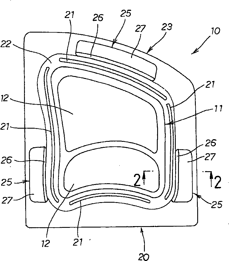
[0031] Such as figure 1 As shown, the punch 11 of the stamping die set 10 is provided with protrusions 12 , 12 . A blank holder 20 is also provided to surround the punch 11 .

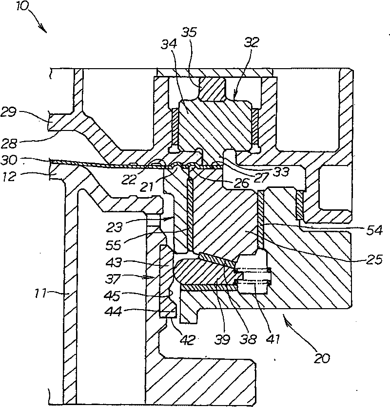
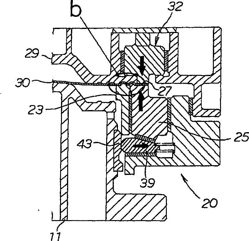
[0032] The blank holder 20 is composed of a first blank holder 23 and a second blank holder 25, 25, 25, the first blank holder 23 has a first bead 21, 21, 21, 21 used as a fixed bead Along with the first holder surface 22 which is a mouth-shaped flat surface, the second blank holders 25, 25, 25 are located inside the first blank holder 23 so as to be able to move in the front-back direction in the figure.

[0033] The second blank holder 25 has a second bead 26 serving as a movable bead and a second holder surface 27 which is an I-shaped flat surface. The second bead 26 is arranged closer to the boss 12 than the second retainer surface 27 , ie more inwardly.

[0034] Specifically, the second bead 26 is provided to the edge of the second holder 25 so as to be closer to the convex portion 12 than the ...


PUM


Abstract

A die set (10) for press-forming a blank of thin metallic sheet (30) is disclosed. The die set has a punch (11) and a blank holder (20). The blank holder has a first bead (21) for restraining an edgeof the blank with a constant force. The first bead is disposed further to an inside than a second bead (26) for restraining the edge of the blank with a force that varies during pressing of the blank.

Description

technical field [0001] The invention relates to a stamping forming technique for drawing and forming thin metal sheets. Background technique [0002] A stamped form can be obtained by placing a blank in a die provided with a recess and drawing the protrusion of a punch into the recess. At this time, when the edge of the blank is held down by the blank holder, a neat formed part without wrinkles can be obtained. However, instead of simply holding down the edge of the blank, it is preferable to adjust the restraining force according to the progress of the stamping, ie drawing process. [0003] In the past, for example, in Japanese Patent Application Laid-Open Publication No. 9-29349 (JP 09-29349A), a punching device capable of adjusting a restraining force has been proposed. use here Figure 9 to describe the proposed stamping device. [0004] Such as Figure 9 As shown, in the stamping apparatus described in JP 09-29349, by effectively having variable point bead 105 in the...

Claims


Application Information

Patent Timeline
Patent Type & Authority Patents(China)
IPC IPC(8): B21D24/04B21D37/12B21D37/10B21D22/22
Inventor 中村健北野泰彦石原好光前田真吾
Owner HONDA MOTOR CO LTD
Learn More