Print head of printer and gap spacer used for the print head

A printing device and printing head technology, applied in printing and other directions, can solve problems such as unable to maintain the gap between the yoke plate and unable to obtain printing pressure

Inactive Publication Date: 2008-08-13
SEIKO PRECISION INC
View PDF2 Cites 2 Cited by
  • Summary
  • Abstract
  • Description
  • Claims
  • Application Information

AI Technical Summary

Problems solved by technology

Proper clearance between yoke plate 58 and print bar 53 cannot be maintained

Method used


Image

  • Print head of printer and gap spacer used for the print head
  • Print head of printer and gap spacer used for the print head
  • Print head of printer and gap spacer used for the print head

Examples


Embodiment Construction

[0039] Next, a print head of a printing device according to an embodiment of the present invention will be described with reference to the drawings.

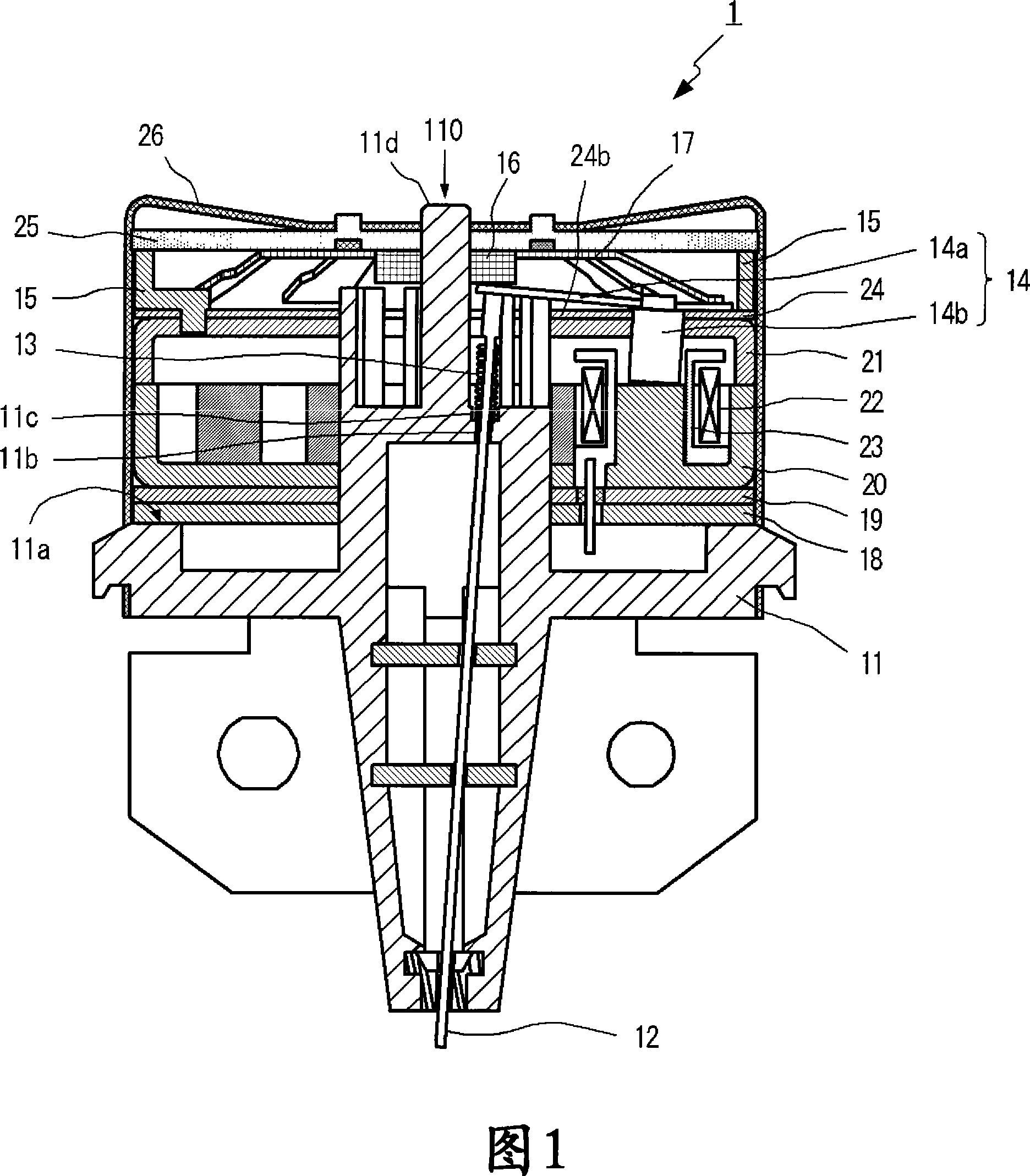
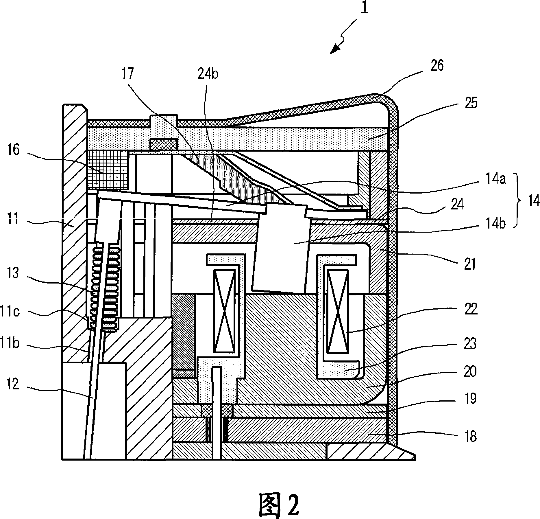
[0040] The configuration of the print head 1 of the printing apparatus according to the present embodiment is shown in FIG. 1 . In addition, a partially enlarged view of FIG. 1 is shown in FIG. 2 .

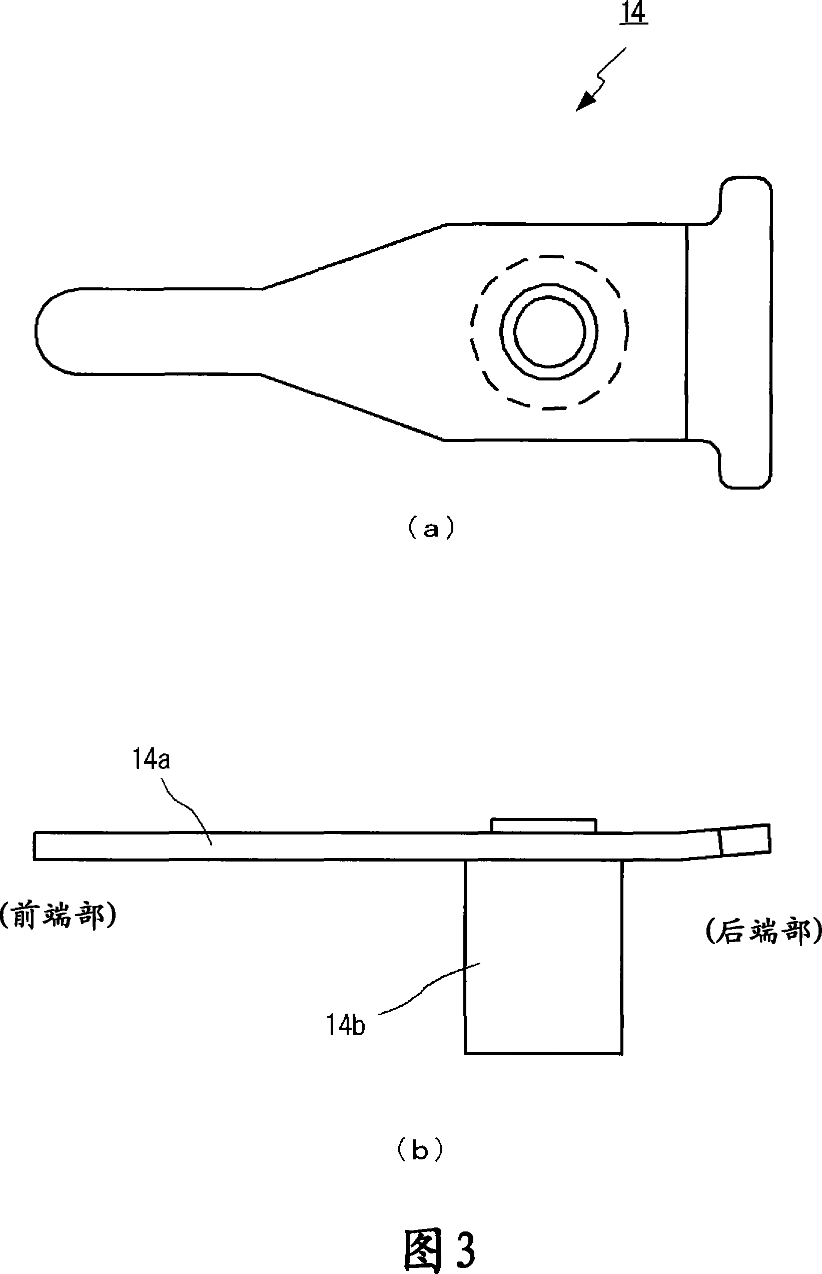
[0041] The print head 1 of the printing device according to this embodiment includes: a needle cartridge 11, a printing needle 12, a return spring 13, a printing lever mechanism part 14, a lever guide part 15, a stopper 16, a lever spring 17, and spacers 18 and 19. , Yoke shell 20, yoke plate 21, drive coil 22, coil frame 23, gap spacer 24, head cover 25, locking spring 26.

[0042] The needle box 11 is used to house components in the print head 1 such as printing needles 12, and may be formed of, for example, plastic. The cross section of the needle box 11 relative to the central axis 110 is circular. FIG. 1 shows a cross sectio...


PUM


Abstract

A print head of a printer capable of continuously holding a proper gap between a yoke plate and a print lever. A gap spacer (24) is inserted between the yoke plate and the print lever (14a). The print lever (14a) is brought into contact with the print lever contact parts (24b) of the gap spacer (24) when printing on a print surface. A cutout part (24a) is formed in the gap spacer (24) so that these nine print lever contact parts (24b) can be independently separated from each other. Accordingly, even if hammering is continuously applied to the gap spacer (24) by the print lever (14a), wrinkles do not occur on the gap spacer (24), and the proper gap can be appropriately held between the yoke plate and the print lever (14a).

Description

technical field [0001] The present invention relates to a print head of a printing device and a gap spacer used in the print head. Background technique [0002] As a printing device, a dot impact type printer has a snap-fit ​​type print head. This print head is a type in which a plurality of print rods are electromagnetically driven (for example, refer to Japanese Patent Application Laid-Open No. 2-39947 (pages 2 and 3, FIG. 1 )). [0003] The mechanism of a conventional snap-fit ​​print head is shown in FIG. 10 . In a conventional print head, as shown in FIG. 10 , a plurality of print pins 52 are slidably held by a yoke pressing frame 51 . The rear end of each print pin 52 is fixed to the front end of the print bar 53 . [0004] The magnetic core 54 is made of a soft magnetic material and has an iron core 54a. The end surface of the iron core 54 a faces the end surface of the print bar 53 . Then, when a current is supplied to the drive coil 55, the iron core 54a is mag...

Claims


Application Information

Patent Timeline
IPC IPC(8): B41J2/235B41J2/275
CPCB41J2/275B41J2/27B41J2/235
Inventor 石川泰田中孝一
Owner SEIKO PRECISION INC
Why Eureka
Try Eureka