Production method for electric device assembly and electric device assembly

A connection structure and electrical connection technology, applied in the direction of conductive connection, structural parts, battery pack components, etc., can solve the problems of increased weight of connecting components, high manufacturing cost, expensive battery modules or battery packs, etc. Heat dissipation effect, ease of manufacturing process, and simplification of structure

Inactive Publication Date: 2008-04-09
PANASONIC CORP
View PDF2 Cites 13 Cited by
  • Summary
  • Abstract
  • Description
  • Claims
  • Application Information

AI Technical Summary

Problems solved by technology

[0010] As described above, in the conventional inter-battery connection structure, two types of connecting members of different shapes corresponding to the series arrangement in the battery axis direction and the parallel arrangement in the radial direction are required, so when configuring a battery module or a battery pack In this case, two types of connecting parts are required, and the cost of parts including metal molds increases accordingly, and the manufacturing cost becomes higher, so the manufactured battery module or battery pack becomes expensive.
In addition, in any connection structure between batteries, two adjacent batteries are connected by welding of connecting members. Therefore, when some batteries are found to be consumed or deteriorated dur

Method used


Image

  • Production method for electric device assembly and electric device assembly
  • Production method for electric device assembly and electric device assembly
  • Production method for electric device assembly and electric device assembly

Examples


Example Embodiment

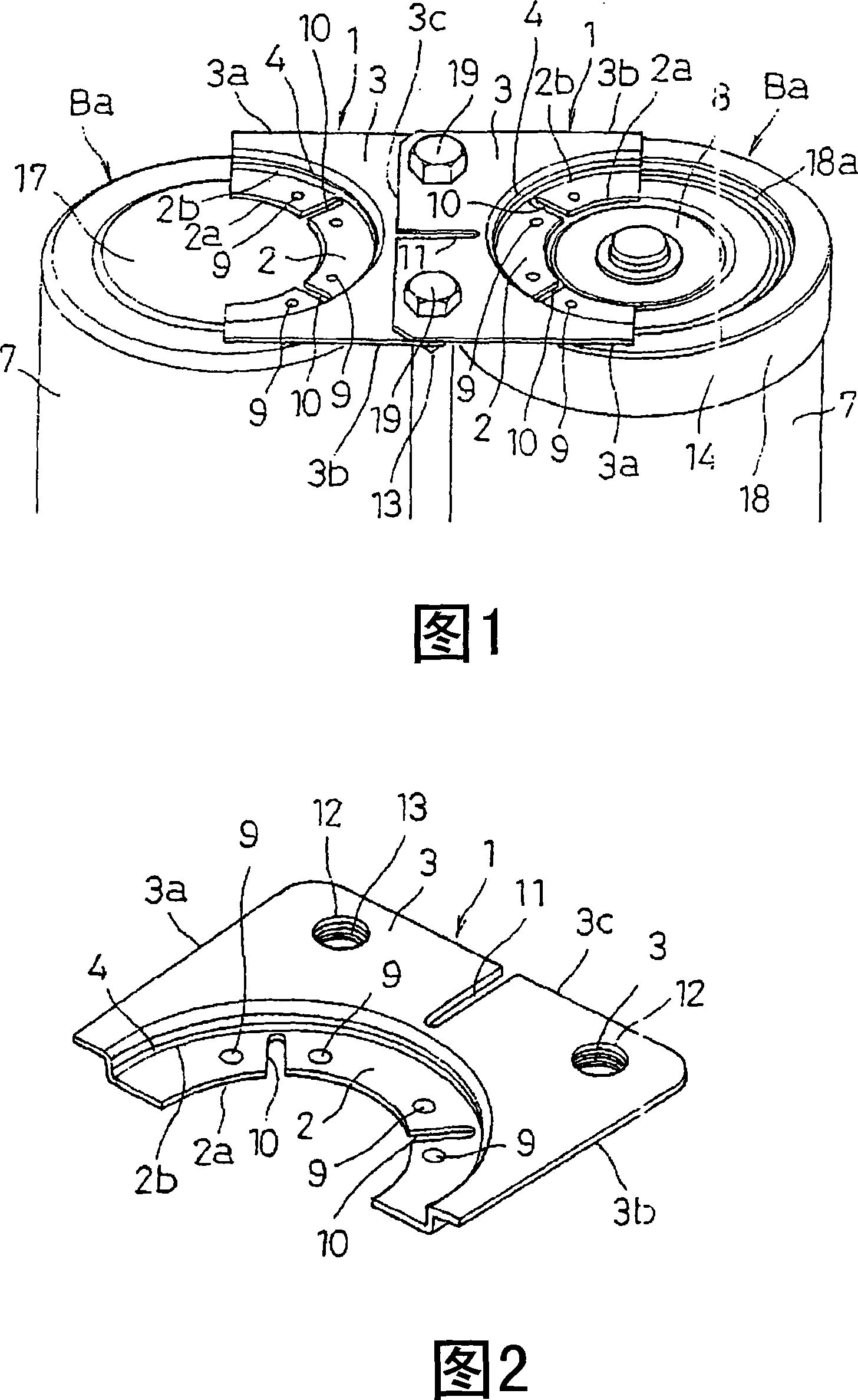
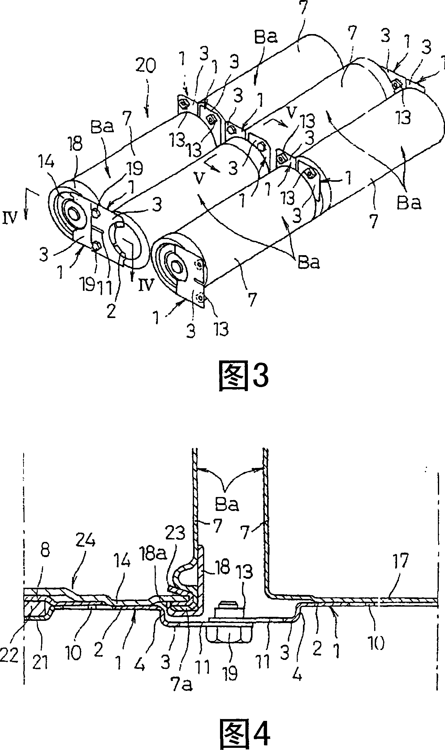
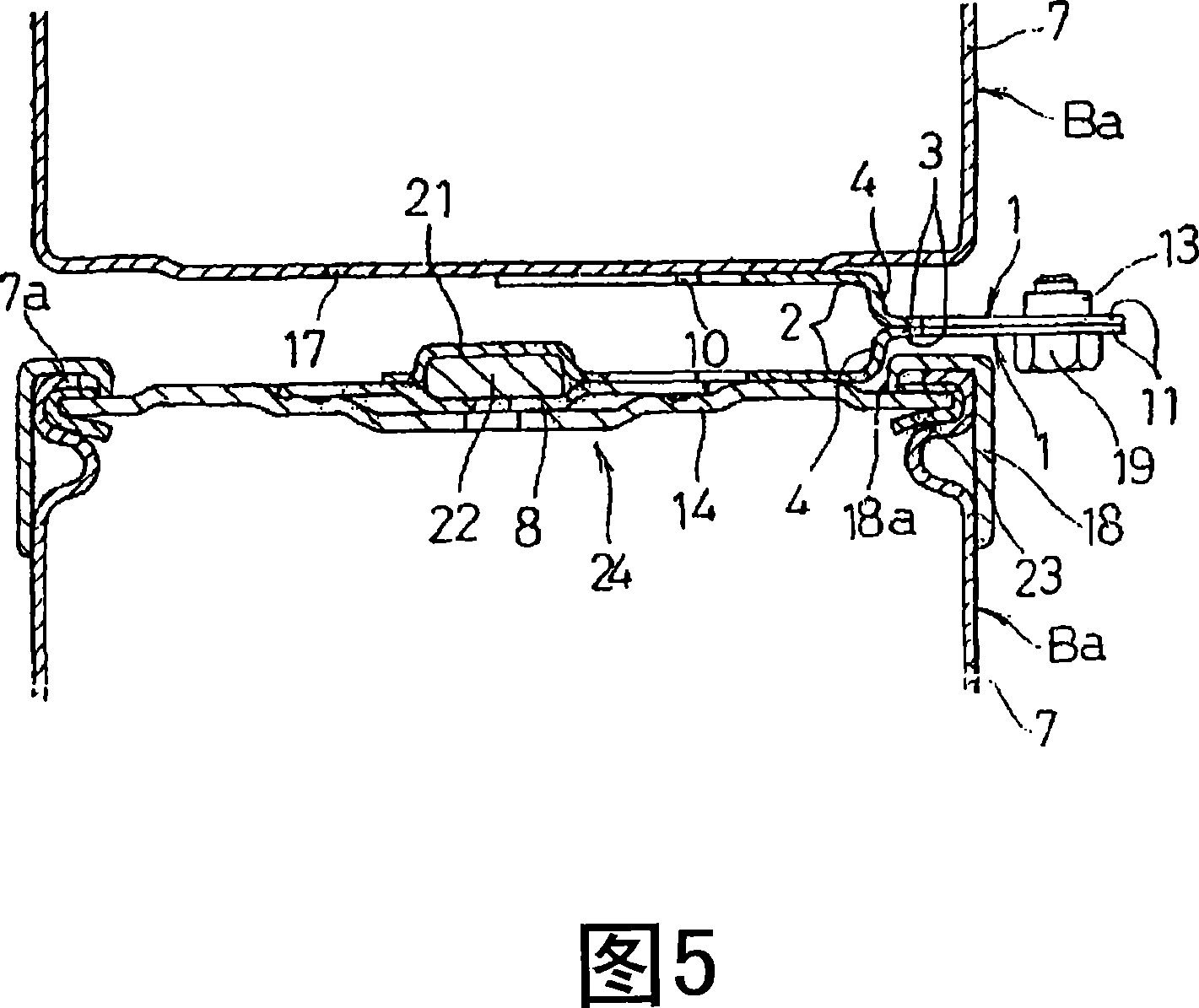
[0039] Hereinafter, preferred embodiments of the present invention will be described with reference to the drawings. FIG. 1 is a perspective view showing a connection structure of an inter-battery connection structure according to an embodiment of the present invention, and FIG. 2 is a perspective view showing an inter-battery connection plate 1 used for the connection. First, the inter-battery connection plate 1 of FIG. 2 will be described. This inter-battery connection plate 1 has a shape that integrally connects the welding portion 2 fixed to the battery case 7 by welding means and the connecting portion 3 extending from the welding portion 2 via a step portion 4, and the welding portion 2 is relatively connected to the connecting plate 1. Part 3 is a recess.

[0040] The welding portion 2 has a semicircular shape included in the circular end surface of the battery case 7 of the battery Ba shown in FIG. 1 . Specifically, it has a shape as follows: a semicircular inner per...


PUM


Abstract

Cell-to-cell connection plates (1) each integrally having a welding part (2) shaped to fall within a circular end of a battery case (7) and a connecting part (2) extending from this welding part (2) are provided. The cell-to-cell connection plates (1) are attached to one electrode terminal and the other electrode terminal of the battery case (7) by welding the welding parts (2), respectively. The connecting parts (3) of the respective cell-to-cell connection plates (1) attached to each adjoining pair of cylindrical batteries (Ba) are overlapped with each other and coupled into electric connection. Consequently, regardless of whether a plurality of cylindrical batteries (Ba) are axially arranged in series or radially juxtaposed, each adjoining two can be connected to each other by using the identical cell-to-cell connection plates (1) for cost reduction. It is also possible to provide a sufficient heat dissipation effect and achieve sufficient robustness and weight saving even when connecting large-sized cylindrical batteries.

Description

technical field [0001] The present invention relates to an inter-battery connection structure for constituting a battery module or a battery pack mainly by connecting a plurality of cylindrical batteries in series or in parallel to obtain a desired output voltage. Background technique [0002] In recent years, the portability and wirelessization of electronic equipment such as AV equipment, personal computers, and portable communication equipment have developed rapidly. As the driving power supply for these electrical equipment, nickel-cadmium batteries or nickel-metal hydride batteries are used because of their high reliability and easy maintenance. , lithium secondary batteries, etc. On the other hand, lead storage batteries are currently the mainstream in applications such as back-up emergency power supplies in the event of power outages caused by disasters such as earthquakes and typhoons, but in the future it is expected to use nickel metal hydride storage batteries wit...

Claims


Application Information

Patent Timeline
IPC IPC(8): H01M2/20H01M2/10H01M50/529H01M50/503H01M50/51H01M50/516H01M50/517H01M50/522H01M50/526
CPCY02E60/12H01M2/022H01M2/204H01M6/42H01M50/107H01M50/522H01M50/526H01M50/516H01M50/517H01M50/51H01M50/503H01M50/50H01M50/20
Inventor 福冈孝博加藤正彦
Owner PANASONIC CORP
Why Eureka
Try Eureka