
Method for controlling a linear motor for driving a striking mechanism

A technology of impact device and linear motor, which is applied in the direction of electromechanical devices, portable impact tools, electrical components, etc., and can solve problems such as inapplicability

Inactive Publication Date: 2008-08-20
HILTI AG
View PDF3 Cites 7 Cited by
  • Summary
  • Abstract
  • Description
  • Claims
  • Application Information

AI Technical Summary

Problems solved by technology

Since the forces acting on the mover in single-phase linear motors with salient poles are cyclical in location according to the pole distribution and thus constitute the stopping force of the fixed mover in the zero position, the usual control of the linear motor Units are not suitable for this type of mover without salient poles

Method used


Image

  • Method for controlling a linear motor for driving a striking mechanism
  • Method for controlling a linear motor for driving a striking mechanism

Examples


Embodiment Construction

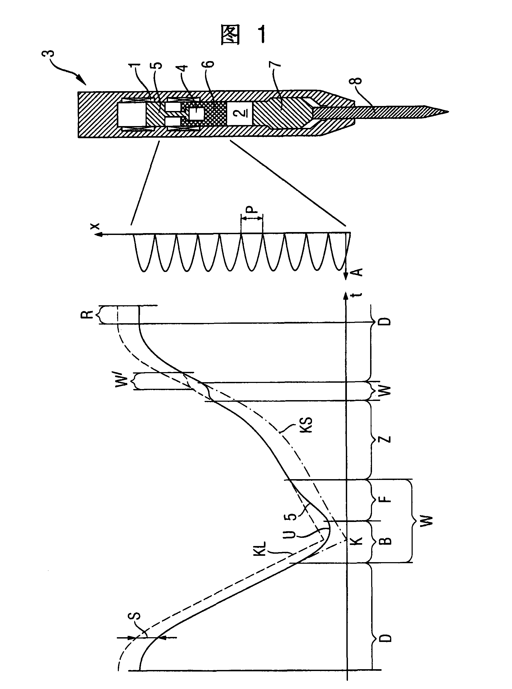
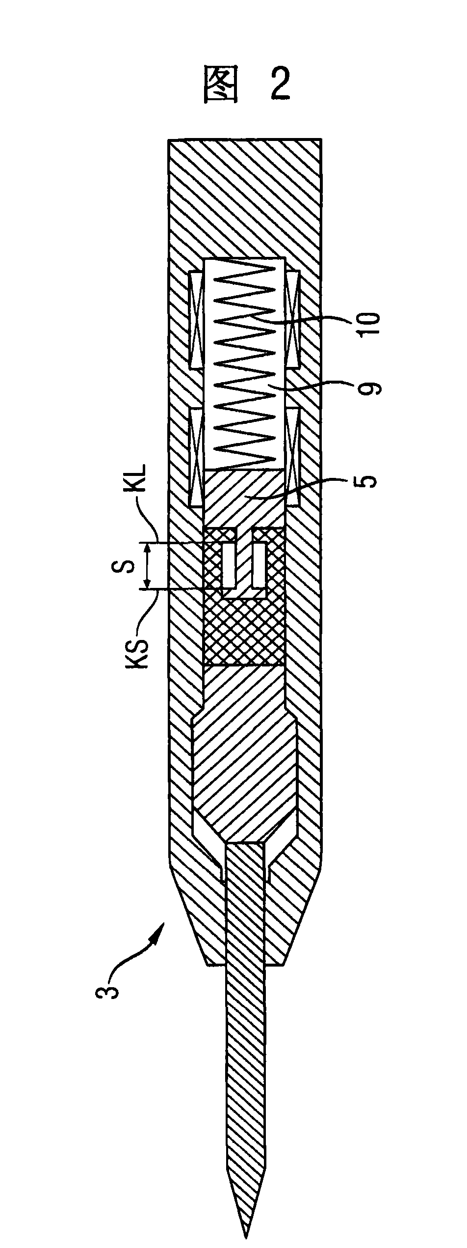
[0019] According to FIG. 1, a method for controlling a single-phase linear motor 1 for driving an impact device 2 of a hand-held power tool 3, which comprises a linear Loose coupling 4 between the regulated mover 5 of the electric motor 1 and the hammer 6 of the impact device 2 , wherein during the described impact cycle exactly one force impact K of the hammer 6 is applied via a punch 7 to Tool 8 on. The impact cycle has a stretching phase Z and a pressing phase D, which each alternate through a change phase W. In the pulling phase Z, the loose coupling 4 bears against the runner-side contact surface KL ( FIG. 2 ) by means of a one-sided forced contact. During the pressurization phase D, the loose coupling 4 bears against the hammer-side contact surface KS ( FIG. 2 ) by means of a one-sided forced contact. In the change phase W, the one-sided forced contact is changed by a contact-free gap length S between the two contact surfaces KL-KS ( FIG. 2 ), wherein in the braking ph...


PUM


Abstract

The invention relates to a controlling method for driving the linear motor of the impacting device, wherein the impacting device has a coupling device (4) loose between a mover (5) and a hammer (6), and has a tractive stage and a pressure stage in the impacting period when the hammer applies force to the tools or the punch. In the tractive stage, the coupling device is sticked on the contact surface at the side of the mover through a unilateral forced contact piece, and is sticked on the contact surface at the side of the hammer in the pressure stage. There is a changing stage between the tractive stage and the pressure stage. wherein the unilateral forced contact is changed through a gap length, the mover is adjustablely loose on the unilateral forced contact of the contact surface and builds a unilateral forced contact on the other contact surface, which is divergingly triggered from the changing stage of the tractive stage to the pressure stage through the place relative to the pole periodic of the salient pole of the linear motor.

Description

technical field [0001] The invention relates to a method for controlling a single-phase linear motor comprising a salient pole for driving an impact device comprising a loose ball between the mover of the linear motor and the hammer of the impact device. Coupling, the striking device is preferably part of an at least partially striking electric hand-held power tool. Background technique [0002] According to GB 1396812, in a linear motor designed to drive a percussion device, its soft-magnetic mover is designed directly as a hammer, which impacts directly on the mechanical end of the tool or punch. According to US Pat. No. 4,553,074, a suitable method for controlling a linear motor is known. [0003] According to EP18075, the permanently magnetized mover of the linear motor is connected without salient poles to the hammer via a loose coupling with exactly two contact sides, between which a contact-free gap is formed length. During the drive cycle, the movers controlled by...

Claims


Application Information

Patent Timeline
Patent Type & Authority Applications(China)
IPC IPC(8): B25D11/06B25D11/04H02K33/00
CPCH02K35/02B25D11/064
Inventor R·谢尔A·宾德J·明德勒
Owner HILTI AG
Learn More