
Disk drive having a sector clock that is synchronized to the angular speed of the spindle motor

Active Publication Date: 2006-10-24
WESTERN DIGITAL TECH INC
View PDF7 Cites 223 Cited by
  • Summary
  • Abstract
  • Description
  • Claims
  • Application Information

AI Technical Summary

Benefits of technology

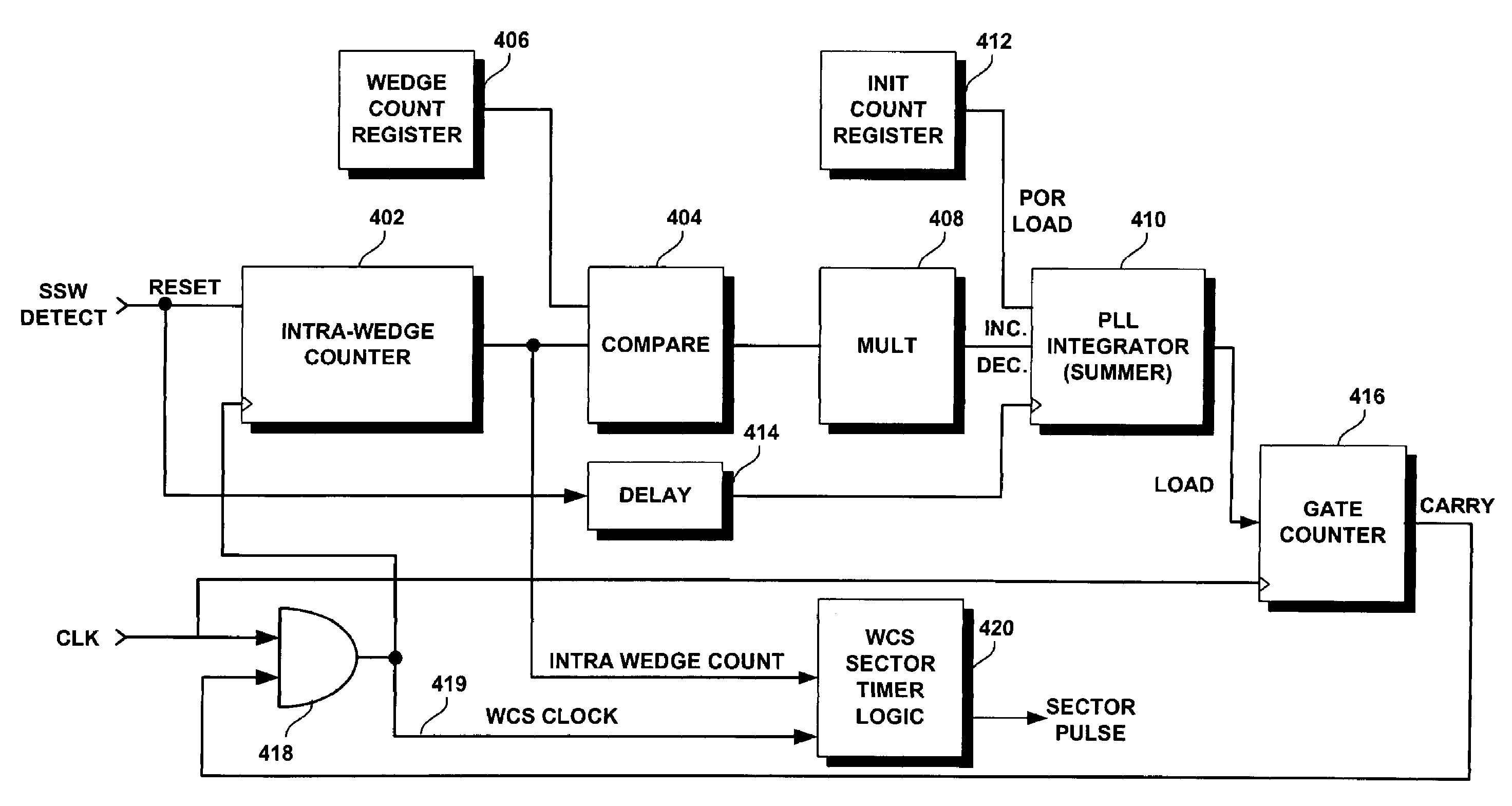
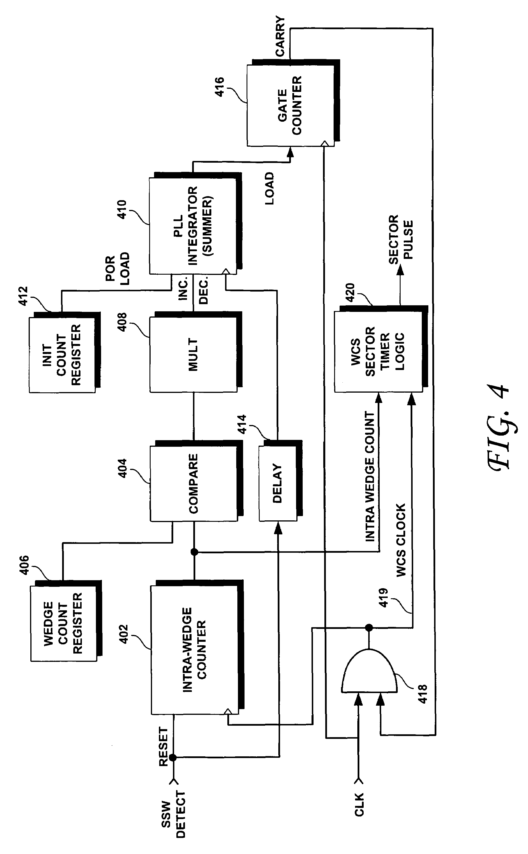
[0012]Accordingly, this invention may be regarded as a disk drive, including a spindle motor and a disk that includes a recording surface having a track that includes a first servo wedge and a second servo wedge and a first addressable location and a second addressable location, each of the servo wedges and each of the addressable locations having a leading end and a trailing end, the disk being driven by the spindle motor to rotate at an angular velocity that is subject to variation, the first addressable location having both its leading end and trailing end between the trailing end of the first wedge and the leading end of the second wedge, and the second addressable location having its leading end between the trailing end of the first wedge and leading end of the second wedge. A head is provided for performing an operation in which the head is maintained adjacent the track and produces a read signal that has multipl

Problems solved by technology

However, the spindle motor does not, in practice, drive the disks at a perfectly constant angular velocity.
This results in maximum uncertainty just before the detection of the next servo sync word.

Method used


Image

  • Disk drive having a sector clock that is synchronized to the angular speed of the spindle motor
  • Disk drive having a sector clock that is synchronized to the angular speed of the spindle motor
  • Disk drive having a sector clock that is synchronized to the angular speed of the spindle motor

Examples


Embodiment Construction

[0026]The present invention enables the generation of more predictably timed sector pulses by accounting for variations in the actual spindle motor speed from its nominal value. If the sector pulses are generated more predictably, the width of the guard bands around the data sectors may be decreased. In turn, if the width of the guard bands is decreased, more data can fit in between servo wedges and the capacity of the drive can be increased. The present invention, according to an embodiment thereof, measures the actual angular velocity of the spindle motor by measuring the actual time between servo sync words.

[0027]The present invention also exploits the physical characteristics of the spindle motor to reduce the size of the guard bands around the data sectors. One such characteristic is the inertia of the spindle assembly, which has been found to minimize angular velocity variations greater than the first harmonic of its rotational frequency. Since the servo wedge sample rate is a...


PUM


Abstract

The present invention compensates for variations in the angular velocity of the drive's spindle motor by periodically dropping clocks to a counter based upon the previous servo wedge-to-wedge timing. This enables a substantially constant count to be maintained between servo wedges and allows a more predictable generation of the data sector pulses. A more predictable generation of the data sector pulses enables the size of the guard band preceding each data sector to be decreased and the capacity of the disk to be correspondingly increased.

Description

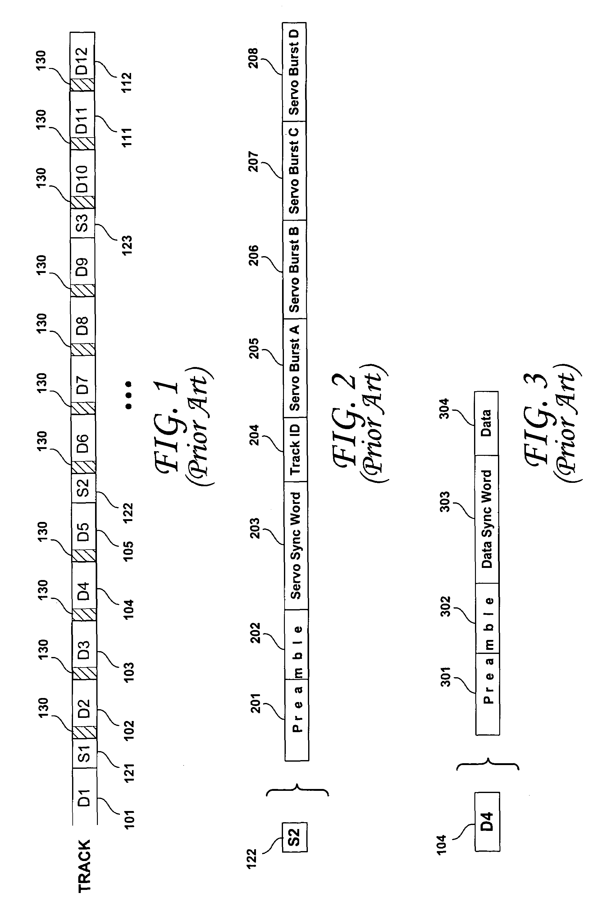
BACKGROUND OF THE INVENTION[0001]1. Field of the Invention[0002]The present invention relates to disk drives. More particularly, the present invention relates to disk drives that vary the timing of the servo detect window according to measured variations in the angular velocity of the drive's spindle motor.[0003]2. Description of the Prior Art[0004]In contemporary magnetic hard disk drives, servo sectors of servo information are interspersed with data sectors circumferentially in concentric tracks around the surfaces of the disk or disks. As shown in FIG. 1, the format of a track of a rigid magnetic disk drive calls for regularly spaced embedded servo sectors (also called servo wedges) (of which representative servo sectors 121, 122, 123 are shown) containing servo information therein. Between the embedded servo sectors are a number of data sectors. There may be an integer number of data sectors between any two servo sectors. However, a track may also include a non-integer number of...

Claims


Application Information

Patent Timeline
IPC IPC(8): G11B5/09
CPCG11B5/5526G11B5/596G11B19/28
Inventor WARREN, JR., ROBERT W.HAGEN, MARK D.
Owner WESTERN DIGITAL TECH INC
Learn More