Sliding track stretching and positioning apparatus

A technology for positioning devices and slide rails, which is applied to furniture parts, household appliances, drawers, etc., and can solve problems such as easy to prevent failure

Active Publication Date: 2008-10-08
KING SLIDE WORKS CO LTD
View PDF7 Cites 10 Cited by
  • Summary
  • Abstract
  • Description
  • Claims
  • Application Information

AI Technical Summary

Problems solved by technology

[0006] The pull-out position of the slide rail is limited by the anti-loosening shrapnel and the stop piece that act separately, so as to prevent the slide rail from falling off and shrinking inwardly, so as to solve the problem that the single shrapnel-type stop structure is easy to prevent failure.

Method used


Image

  • Sliding track stretching and positioning apparatus
  • Sliding track stretching and positioning apparatus
  • Sliding track stretching and positioning apparatus

Examples


Embodiment Construction

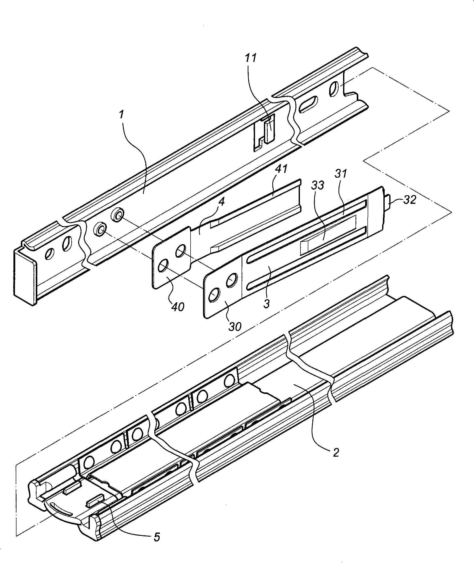
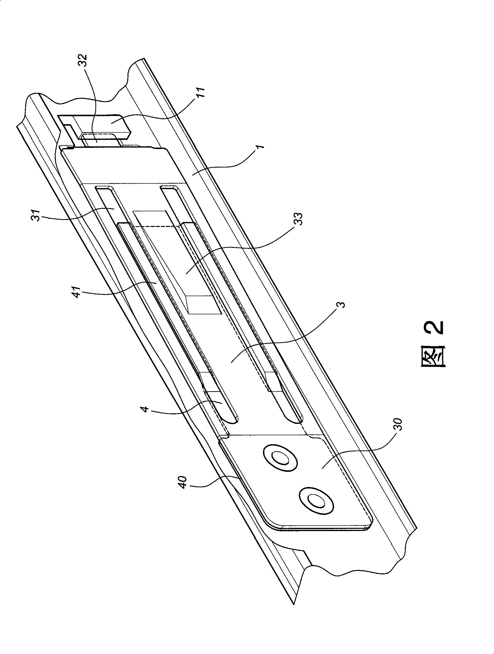
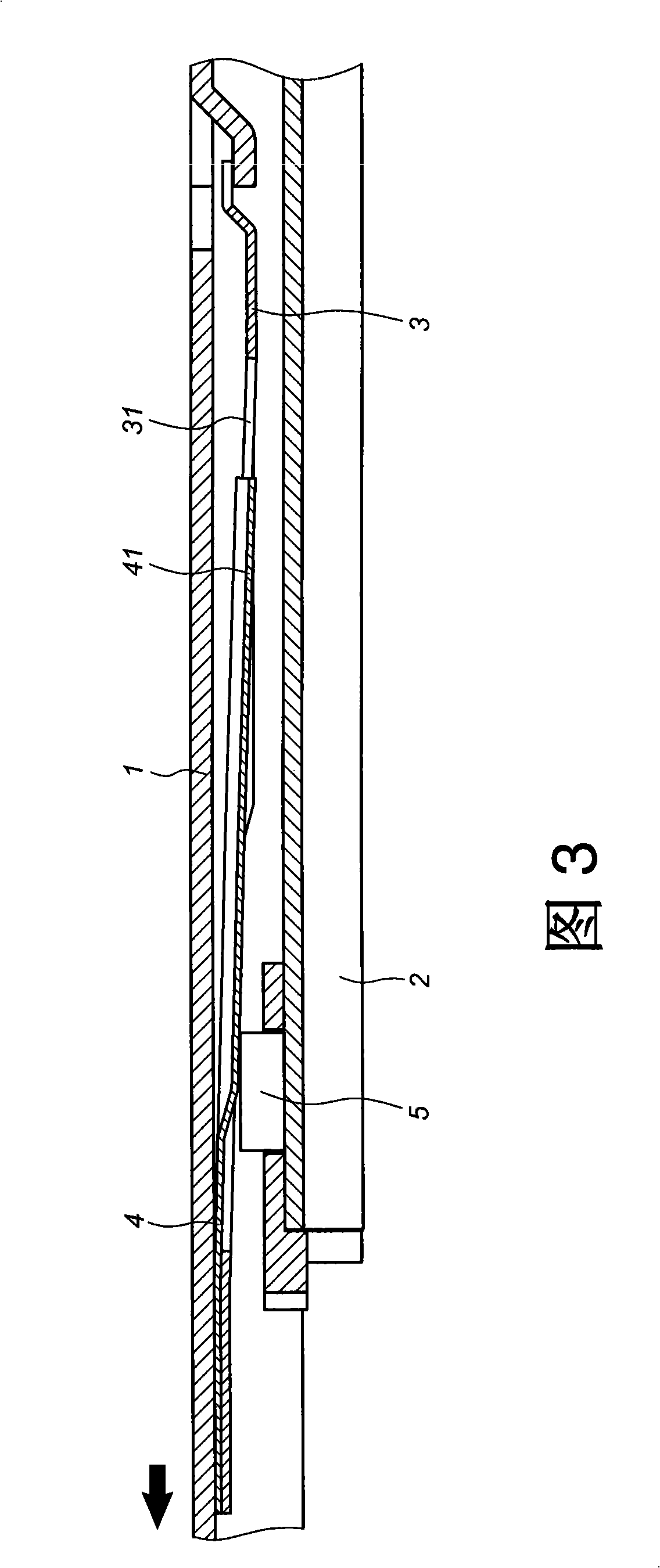
[0020] Such as figure 1 As shown in Fig. 2, the specific embodiment of the present invention includes a first rail 1, a second rail 2, an anti-loosening shrapnel 3, a stopper 4 and a fixing plate 5, wherein:

[0021] The first rail 1 is provided with a limiting piece 11;

[0022] The second rail 2 corresponds to the first rail 1 of the sleeve slide;

[0023] The anti-stripping piece 3 has a fixed end 30, a slot hole 31, a protruding piece 32 and a pressing area 33. The fixed end 30 is fixed on the first rail 1, and the protruding piece 32 is pressed against the limiting piece 11 of the first rail 1. The pressing area 33 is embossed to be pressed by the user;

[0024] The stop piece 4 is located between the anti-loosening elastic piece 3 and the first rail 1, and has a fixed end 40 and a stop portion 41, and the fixed end 40 is fixed on the first rail 1 corresponding to the fixed end 30 of the anti-loosening elastic piece 3 , and the resisting portion 41 is a convex rib and ...


PUM


Abstract

The invention provides a slide-rail tensile positioning device, including a first rail, a second rail, an anti-escaping shrapnel, a retaining sheet and a fixing plate; wherein, the second rail is correspondingly sheathed with the first rail in a sliding way; the anti-escaping shrapnel is provided with a fixed end and a slotted hole and the fixed end is fixed on the first rail; the retaining sheet is provided with a fixed end and a retaining part; the retaining sheet is arranged between the anti-escaping shrapnel and the first rail and the fixed end is fixed on the first rail corresponding to the fixed end of the anti-escaping shrapnel; the retaining part is correspondingly inserted in the slotted hole of the anti-escaping shrapnel and the fixed plate is fixed on the second rail corresponding to the slotted hole of the anti-escaping shrapnel.

Description

technical field [0001] The invention relates to a slide rail stretching and positioning device, in particular to a slide rail stretching and positioning device which utilizes double shrapnel types to limit the pull-out position of the slide rail, and at the same time has the blocking effect of preventing the slide rail from detaching and preventing inward shrinkage . Background technique [0002] At present, the general slide rail design, those with stronger functions, have a kind that can prevent the movable rail body from shrinking easily and slide into the fixed rail body after the movable rail body is pulled out, that is, the movable rail body is locked. It is used to fix the rail body to prevent the movable rail from shrinking in the stretched state, and this kind of anti-shrinkage positioning function can be divided into two modes: "firm locking" and "elastic temporary positioning". Among them, "firm locking" "For those who need to cooperate with the unlocking control...

Claims


Application Information

Patent Timeline
IPC IPC(8): A47B88/04A47B88/16
Inventor 陈庚金黄石龙王俊强
Owner KING SLIDE WORKS CO LTD
Why Eureka
Try Eureka