Through-flow double channel blower fan

A dual-channel, fan technology, applied in the direction of mechanical equipment, machines/engines, liquid fuel engines, etc., can solve the problems of uneven wind speed, non-adjustable wind speed at the air outlet, and inability to achieve graded winnowing, etc., to achieve a uniform distribution effect

Inactive Publication Date: 2008-10-15
SHANDONG UNIV OF TECH +1
View PDF0 Cites 6 Cited by
  • Summary
  • Abstract
  • Description
  • Claims
  • Application Information

AI Technical Summary

Problems solved by technology

The main problems are: the wind speed of the air outlet is not adjustable, the wind speed is not uniform, and because the existing fan only has one air outlet, it cannot achieve classified winnowing, and its working performance needs to be further improved

Method used


Image

  • Through-flow double channel blower fan
  • Through-flow double channel blower fan
  • Through-flow double channel blower fan

Examples


Embodiment Construction

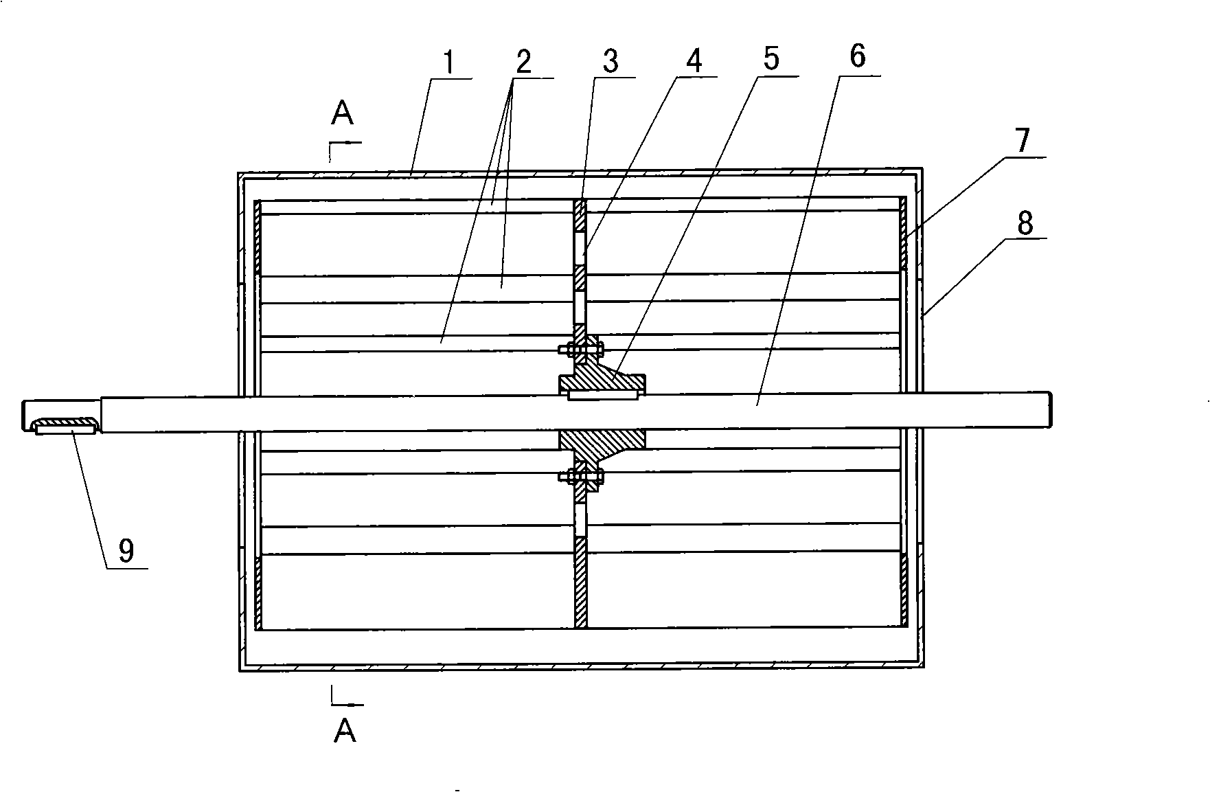
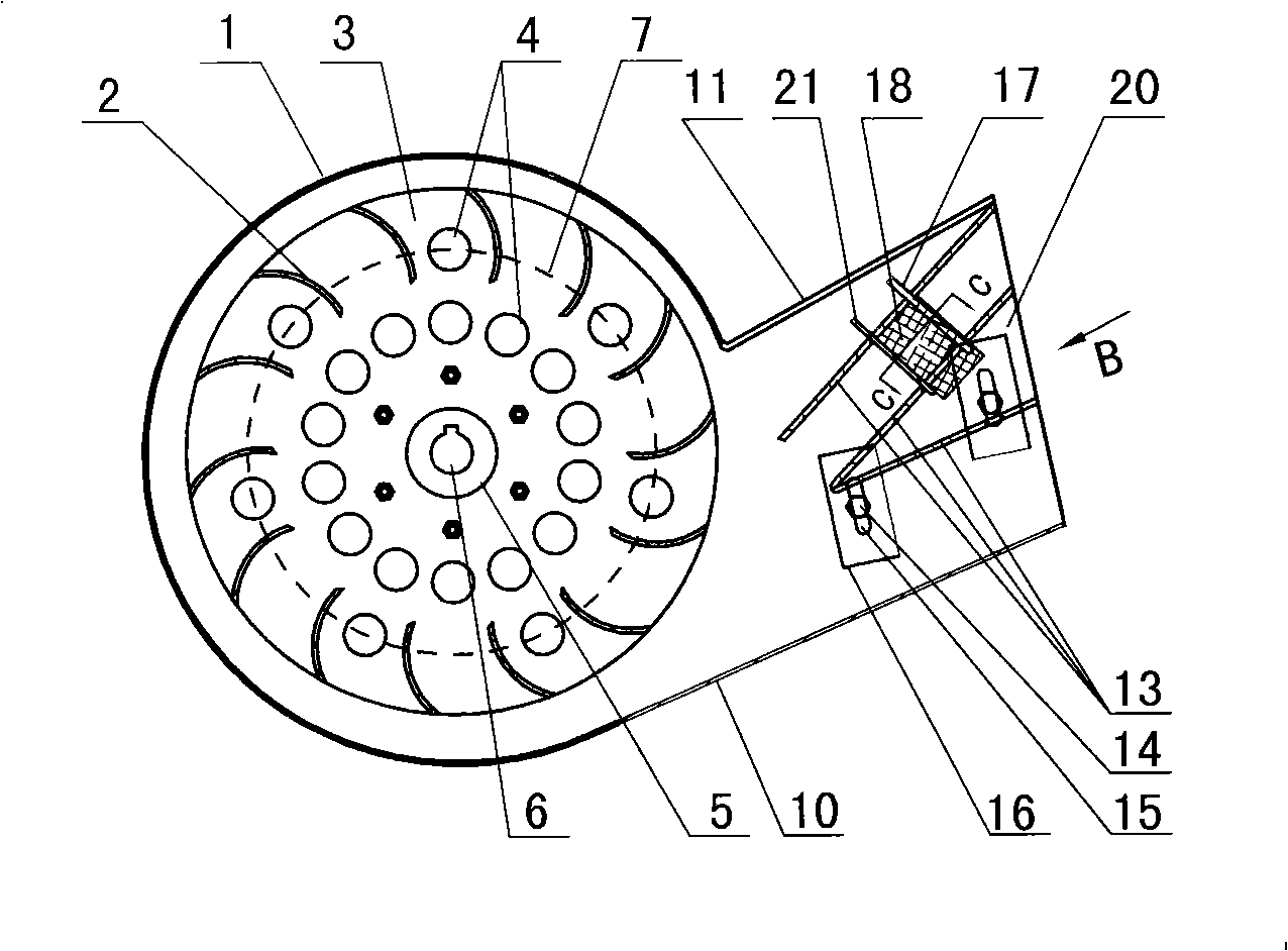
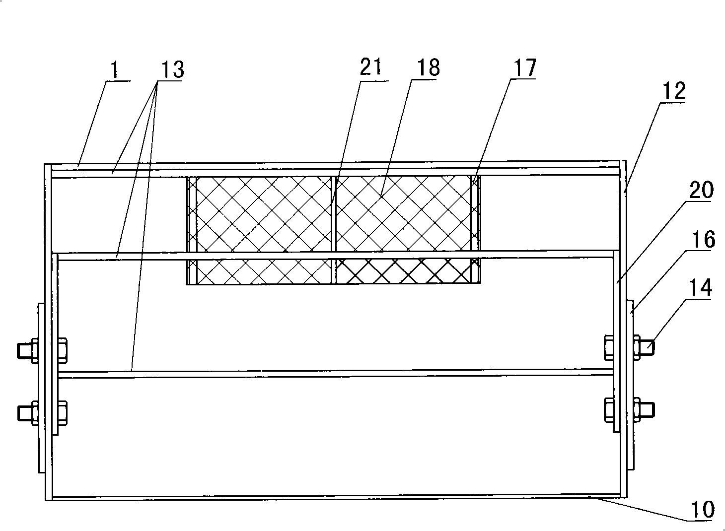
[0018] exist Figure 1-4 In the shown embodiment, it includes a volute 1 with an air inlet 8 and an air outlet and an impeller assembly, wherein the cross section of the air outlet and the outer port are square, and the bottom plate 10 forming the air outlet is at an angle of 25 degrees to the horizontal , from the outer end of the air outlet, three partitions 13 are respectively arranged inwardly, wherein the outer end of the first partition 13 is fixedly connected with the outer end of the top plate 11 constituting the air outlet, and the included angle with the top board 11 of the air outlet is 18 degrees, the second partition 13 is located between the first and third partitions 13, and is parallel to the first partition 13, and the third partition 13 is parallel to the bottom plate 10 forming the air outlet, and its probe The inner end of the air inlet and outlet is fixedly connected with the inner end of the second partition 13, and the side plate 12 close to the air outl...


PUM


Abstract

The invention provides a cross flow two-channel blower which comprises a spiral casing provided with a wind inlet, a wind outlet and an impeller assembly; the invention is characterized in that a cross section and an outer port of the wind outlet are of parallelograms; the wind outlet is inside provided with three clapboards for dividing a wind channel into an upper wind channel and a lower wind channel with two adjustable longitudinal sections; the cross section of each wind channel is a parallelogram; the wind channel positioned on the upper part is blocked with a cambered sieve vertical tothe wind channel; the sieve is positioned in the middle of the wind channel; the arc length of the sieve is 1/2 to 2/3 of the width of the wind channel; the circle center of the sieve is positioned on one side of the sieve near the outer end of the wind outlet; the upper end of the sieve is fixedly connected with the first clapboard; two sides of the sieve wind on a guide pole vertical to the first clapboard; the lower end of the sieve is inserted into a cambered groove on the second clapboard arranged for the sieve; and the lengths of the three clapboards are less than the distance between the outer end of the wind outlet and an volute angle of the wind outlet. The blower can adjust the wind speed and wind pressure of the two wind channel outlets and has uniform airflow distribution and good working performance.

Description

technical field [0001] The invention provides a cross-flow double-channel fan, which is used in the technical field of cleaning and classifying machinery. Background technique [0002] Existing fans are mainly composed of the volute of the air inlet and outlet and the impeller assembly, wherein the impeller assembly is composed of a flange connected to the side plate, a rotating shaft and a plurality of straight blades, and the plurality of straight blades are fixedly connected at a certain distance On the fan shaft, the function of the flange is to fix the impeller assembly and the volute. During its working process, the fan is driven by the motor to drive the impeller assembly to rotate in the volute, the gas is sucked by both ends of the impeller assembly, the blades force the gas to rotate, and do work on the gas to increase its energy. The gas under the action of centrifugal force It is thrown out around the rotating shaft, and the speed energy is converted into pressu...

Claims


Application Information

Patent Timeline
Patent Type & Authority Applications(China)
IPC IPC(8): F04D29/00F04D29/30F04D25/08
Inventor 郭志东杜瑞成任传波朱金光倪国庆
Owner SHANDONG UNIV OF TECH
Why Eureka
Try Eureka