Method and apparatus for improving main rotor yoke fatigue life

A technology for rotors and rotorcraft, which is applied to rotorcraft, transportation and packaging, motor vehicles, etc., and can solve problems such as increased yoke life

Inactive Publication Date: 2008-10-15
BELL HELICOPTER TEXTRON INC
View PDF0 Cites 4 Cited by
  • Summary
  • Abstract
  • Description
  • Claims
  • Application Information

AI Technical Summary

Problems solved by technology

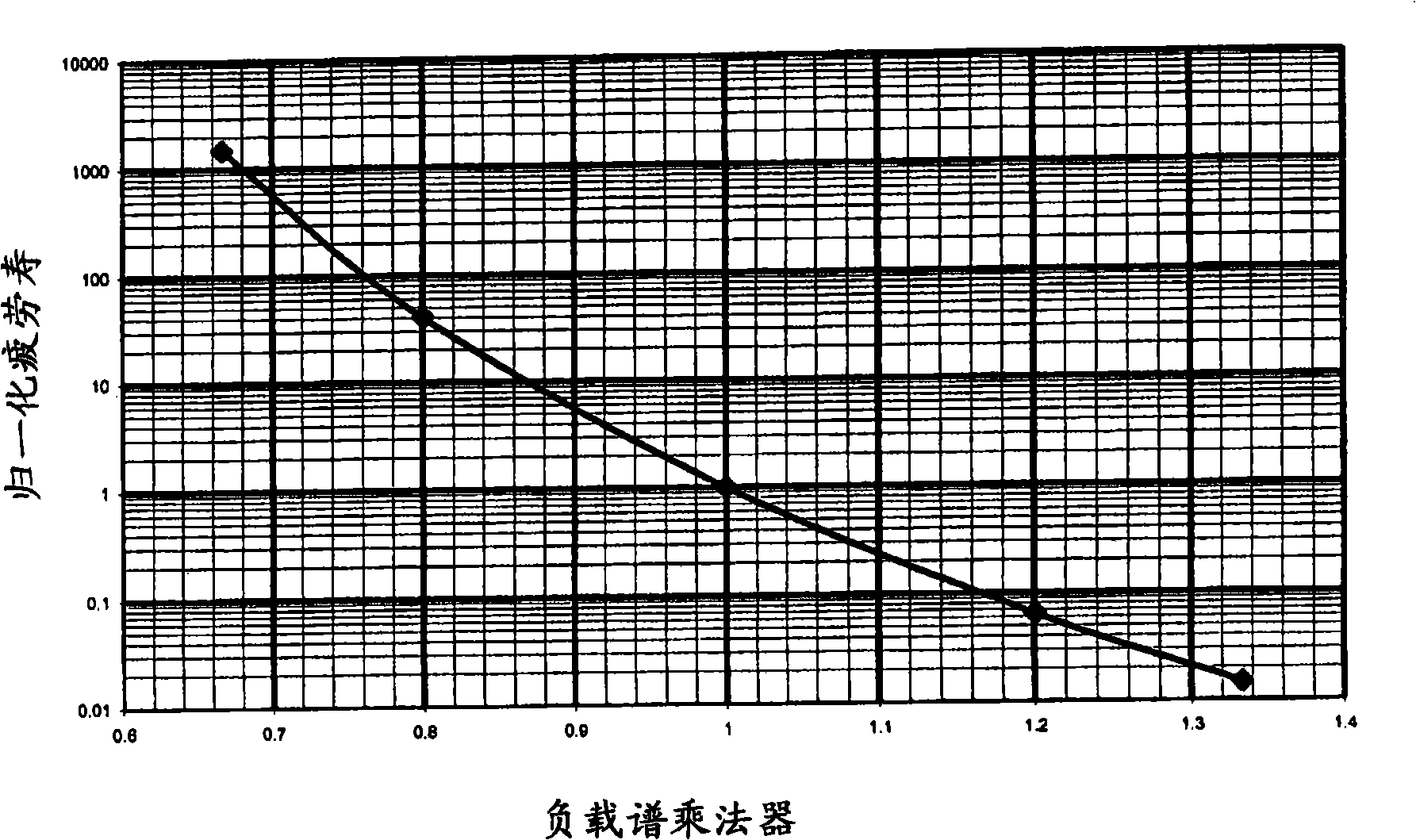
Thus, even a 10% reduction in average yoke loadin

Method used


Image

  • Method and apparatus for improving main rotor yoke fatigue life
  • Method and apparatus for improving main rotor yoke fatigue life
  • Method and apparatus for improving main rotor yoke fatigue life

Examples


Embodiment Construction

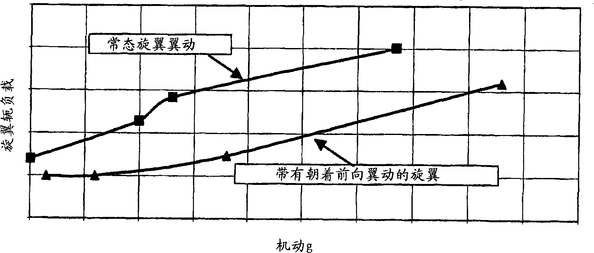
[0017] Efficient and reliable measurements of rotor wing motion are understandably difficult to accomplish. However, it is known that rotor motion consists of two components. The first component is the thrust coefficient C of the rotor T and a function of the advance speed ratio μ. C T is a function of the collective control position of the rotor, and μ is a function of the helicopter's flight speed (airspeed). The second wing motion component is a function of the cyclic control input to the rotor, primarily the longitudinal cycle. Therefore, the total rotor motion can be accurately estimated using the longitudinal period input, the collective position, and the measured (true) flight speed. Advantageously, these three parameters are readily available parameters that are measured in most rotorcraft.

[0018] In one embodiment, sensors or encoders are used to measure the longitudinal period and collective control positions. In addition, the flight speed sensor can be used ...


PUM


Abstract

The present invention provides a method and system for optimizing rotor flapping, which utilizes the collective stick position and true airspeed to determine a commanded longitudinal stick position.

Description

[0001] Cross References to Related Applications [0002] This application claims priority to US Patent Application Serial No. 11 / 215,317, filed August 31, 2005, which is incorporated by reference in its entirety. [0003] government rights [0004] This invention was made with Government support under Contract No. N00019-96-0128 awarded by the (United States) Department of the Navy. The (US) Government has certain rights in this invention. Background technique [0005] It is known in the rotorcraft industry that excessive flapping of rotors, such as those used in flexure beam systems, can greatly shorten the life of the rotor yoke. [0006] Although rotor flex is necessary for optimal flight control, it is desirable to obtain such control without shortening the life of the yoke, which is an extremely expensive component to replace. Such as figure 1 As shown, it has been determined that a small reduction in oscillatory yoke loading can lead to a significant increase in yoke...

Claims


Application Information

Patent Timeline
IPC IPC(8): B64C27/00B64C27/54B64C27/56B64C27/57G05D1/08
CPCB64C27/57B64C27/001B64C27/00B64C27/54G05D1/08
Inventor A·阿格尼霍特里H·凯尔泽J·席林斯R·福滕博
Owner BELL HELICOPTER TEXTRON INC
Why Eureka
Try Eureka