Thin spring hinge mechanism of glasses temple

A spring hinge and temple technology, applied in the directions of glasses/safety glasses, glasses/goggles, optics, etc., can solve the problems of wear of the peripheral part of the pivot of the hinge, complicated assembly of the glasses frame, loosening of the fixing screws, etc. The effect of hinge shake suppression, high fashion and simple structure

Inactive Publication Date: 2008-11-12
上海野尻光学有限公司
View PDF1 Cites 0 Cited by
  • Summary
  • Abstract
  • Description
  • Claims
  • Application Information

AI Technical Summary

Problems solved by technology

Although this structure intends to design the temple with a thin plate-like appearance, the appearance of the temple is damaged due to the arc-shaped tongue installed on the connecting part
Furthermore, since the end of the tongue acting on the leaf spring is arranged at a position deviated from the fulcrum, that is, the hinge, when the leaf spring is pressed, the load applied to the hinge from the acting portion of the tongue becomes large, which causes the pivot peripheral portion of the hinge to Wears out fast and the hinge sometimes wobbles
This structure also discloses a method of fixing the leaf spring with a screw member, but this method not only complicates the assembly of the spectacle frame, but also the repeated opening and closing operations of the temple will loosen the fixing screw, and sometimes it is impossible to remove the leaf spring from the plate. The spring gets proper rebound force

Method used


Image

  • Thin spring hinge mechanism of glasses temple
  • Thin spring hinge mechanism of glasses temple
  • Thin spring hinge mechanism of glasses temple

Examples


Embodiment 1

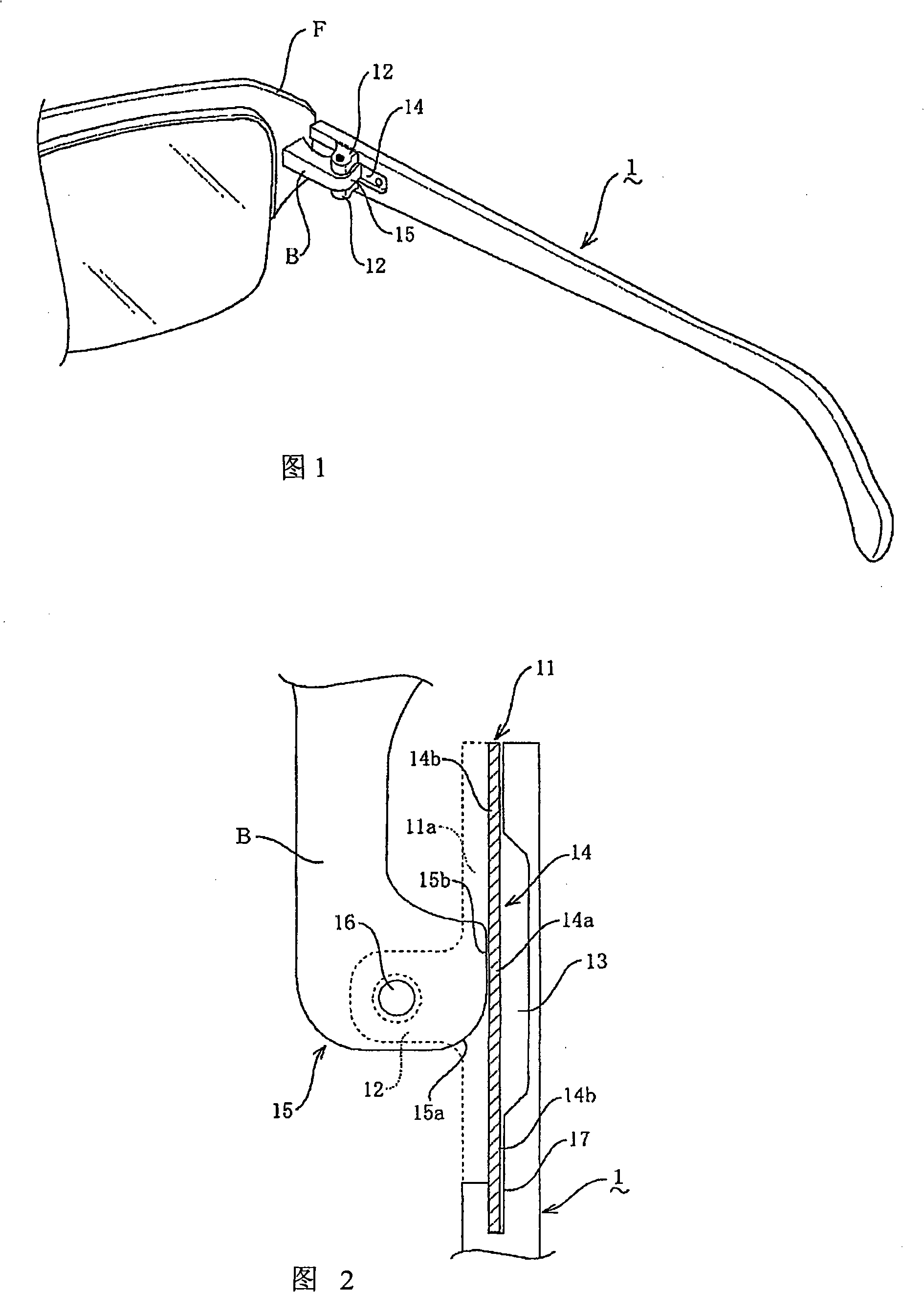
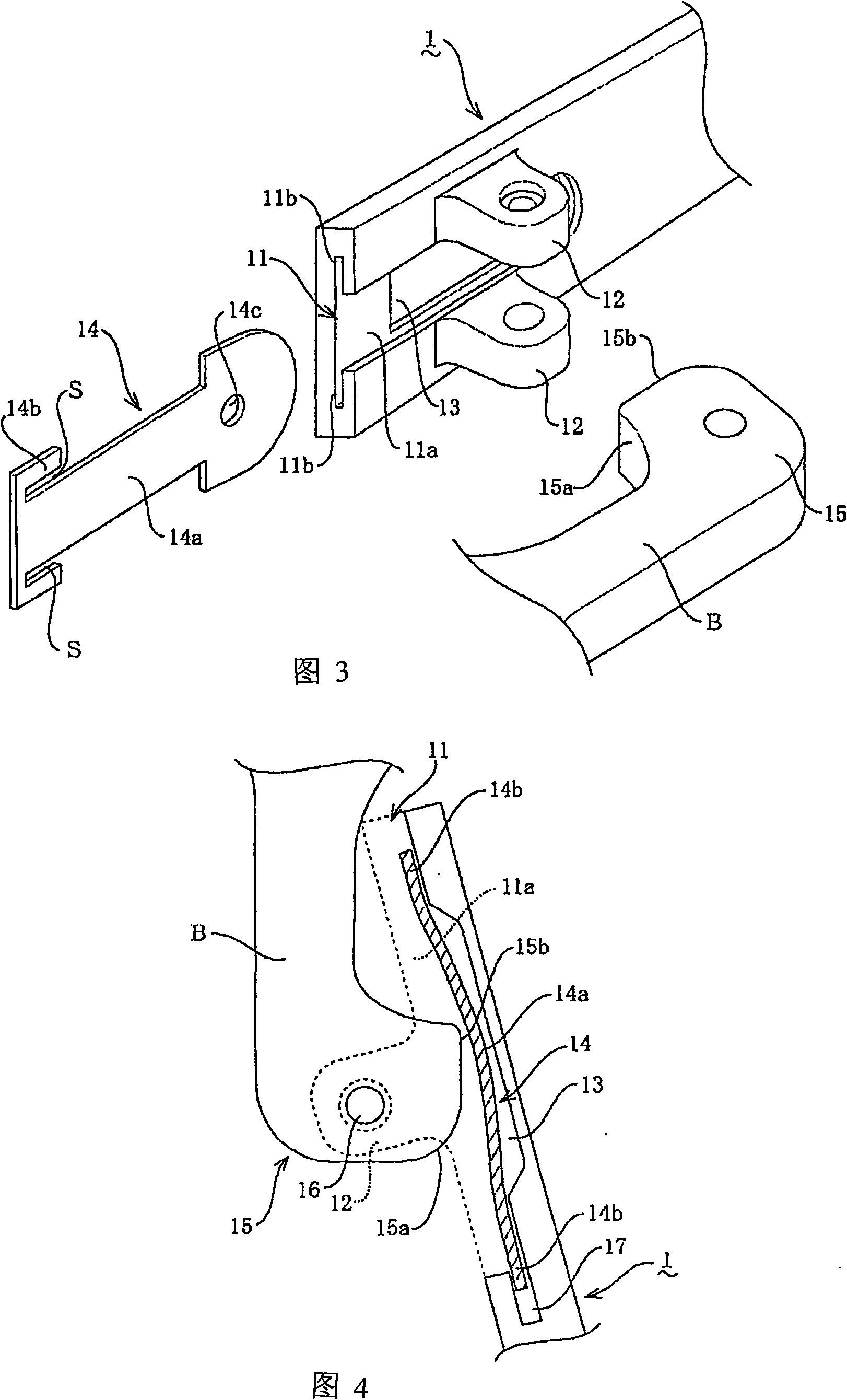
[0025] Referring to FIGS. 1 to 4, an insertion groove 11 having an opening 11a on the inner surface side is provided at the front end of a band-shaped metal temple 1, and the opening of the insertion groove 11 is sandwiched between the upper and lower sides of the temple. The opposite of 11a is provided with a butterfly piece 12 (see Fig. 1, Fig. 2). On the outer surface side of the inner wall of the insertion groove 11 of the temple 1, a relief hole 13 is formed at the position corresponding to the butterfly piece 12, and a sheet-shaped leaf spring 14 is installed in the insertion groove 11b of the insertion groove 11 (see FIG. 3 ). In this embodiment, the material of the leaf spring 14 is SK steel which is cheap and easy to form. Of course, stainless steel which is not easy to rust, copper alloys such as beryllium copper, titanium alloys, etc. can also be used.

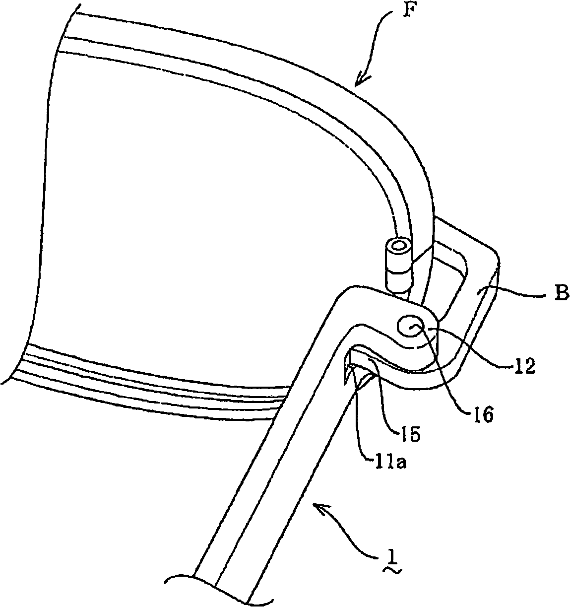
[0026] Between the two butterfly pieces 12 of the temple 1, a rotating butterfly piece 15 is inserted, and the r...

Embodiment 2

[0033] see Figure 5 ~ Figure 7 , the same as Embodiment 1, the difference is that in this embodiment, the insertion tunnel 11 having the opening 11a is provided on the outer surface side of the temple 1, between the butterfly pieces 12 that are provided sandwiching the opening 11a , insert the rotating butterfly 15 formed on the rear end of the bracket B connected with the side end of the front frame F and perform hinge connection, by means of this, when the temple 1 is opened to the outside, the protrusion of the rotating butterfly 15 The curved portion 15b bends the leaf spring 14 inwardly, and can impart a rebound force to the opening and closing operation of the temple 1 (see Figure 5 , Figure 6a, Figure 6b).

[0034] And in the present embodiment, the inner side of the temple 1 is punched to form a relief hole 13, because the deformation of the leaf spring 14 is not limited by the thickness of the temple 1, so the leaf spring 14 can be bent beyond the thickness of the t...

Embodiment 3

[0037] see Figure 8 , Fig. 9, the same as Embodiment 1, the difference is that in this embodiment, a temple 1 made of plastic is used, and the middle area part has a bending part 14d in the insertion groove 11 of the temple 1. With this structure, when the temple 1 is opened to the outside, the convex portion 15b of the rotating disc 15 presses the bending portion 14d to make it bend. With this, the deformed bending portion can be utilized. The elastic action of 14d exerts a force on the temple 1 (refer to Figure 8 and Figure 9a , Figure 9b ). Moreover, the temple 1 without the leaf spring 14 can be made thinner. In addition, when the leaf spring 14 is deformed, no local load is applied to the insertion groove 11. Therefore, even a plastic temple with relatively low rigidity There is no deformation, and there is no problem in using it.

[0038] Cutouts 17 are formed at the front and rear of the insertion groove 11 of the temple 1 , and the leaf spring 14 is tightly fi...


PUM


Abstract

A thin spring hinge mechanism of an eyeglass temple mainly includes a temple (1), a front frame (F) and a bracket (B) connected with the front frame (F), wherein, the front end part of the temple (1) is provided with an inserting groove which has open parts arranged on the inner surface side and the outer surface side; tabs are arranged on the upper or/and the lower parts of the open parts; a yielding hole (13) is arranged on the temple (1); an embedded groove (11b) is arranged in an inserting groove (11); a plate spring (14) is arranged in the embedded groove (11b); a revolving tab (15) is arranged on the extending end of the bracket (B) and the revolving periphery of the revolving tab presents a cam shape; the revolving tab (15) is provided with a pivot (16) which connects a tab (12) with the revolving tab (15) in a hinge way; ; an convex part (15b) of the cam periphery of the revolving tab contacts with the plate spring (14). In the thin spring hinge mechanism of the eyeglass temple, the situation that the structure does not hinder the open-close function of the temple for the loose of the hinge or the fixing screw cannot happen, the structure is simple and the production cost is low.

Description

technical field [0001] The invention relates to the improvement of the temple of the glasses, in particular to a thin spring hinge machine for the temple of the glasses. Background technique [0002] In general spectacle frames, in order to stabilize the wearing of the temples on both sides of the head, when the temples are opened, the spring hinge mechanism is used to force the temples to the inside and generate a large rebound force when the temples are opened. [0003] The spring hinge mechanism of the known spectacle frame is that a helical spring is housed in the hinge connection part of the temple, and the helical spring is compressed when the temple is opened, and utilizes the rebound force of the compression to apply force to the inner side of the temple (see Japanese Patent Application Laid-Open No. 6-242406, pages 2 to 5, Figures 1 to 3)). However, in the above-mentioned known spring hinge mechanism, in order to accommodate the coil spring, a cylindrical mounting ...

Claims


Application Information

Patent Timeline
Patent Type & Authority Applications(China)
IPC IPC(8): G02C5/22
CPCG02C5/2254G02C5/10G02C2200/22
Inventor 水口秀则
Owner 上海野尻光学有限公司
Why Eureka
Try Eureka