Sweeper for dredging underground pipeline

A technology for underground pipelines and cleaners, which is applied in the field of cleaners for dredging underground pipelines. It can solve problems such as difficulty in dredging pipelines, limitation of pipe length, and impact on cable laying quality, and achieves the effect of overcoming resistance and good contact

Active Publication Date: 2008-11-19
WUXI POWER SUPPLY JIANGSU PROVINCE ELECTRIC POWER +1
View PDF0 Cites 16 Cited by
  • Summary
  • Abstract
  • Description
  • Claims
  • Application Information

AI Technical Summary

Problems solved by technology

[0004] In the prior art, the construction site generally dredges the pipes by manpower pulling plastic rods. The disadvantages of this dredging method are: large loss and relatively large restrictions on the length of the pipes
With the gradual promotion of non-excavation technology, the length of some river-crossing pipes is too long, and the current rods cannot be used at all, which makes it difficult to dredge the pipes and affects the quality of cable laying.

Method used


Image

  • Sweeper for dredging underground pipeline
  • Sweeper for dredging underground pipeline
  • Sweeper for dredging underground pipeline

Examples


Embodiment Construction

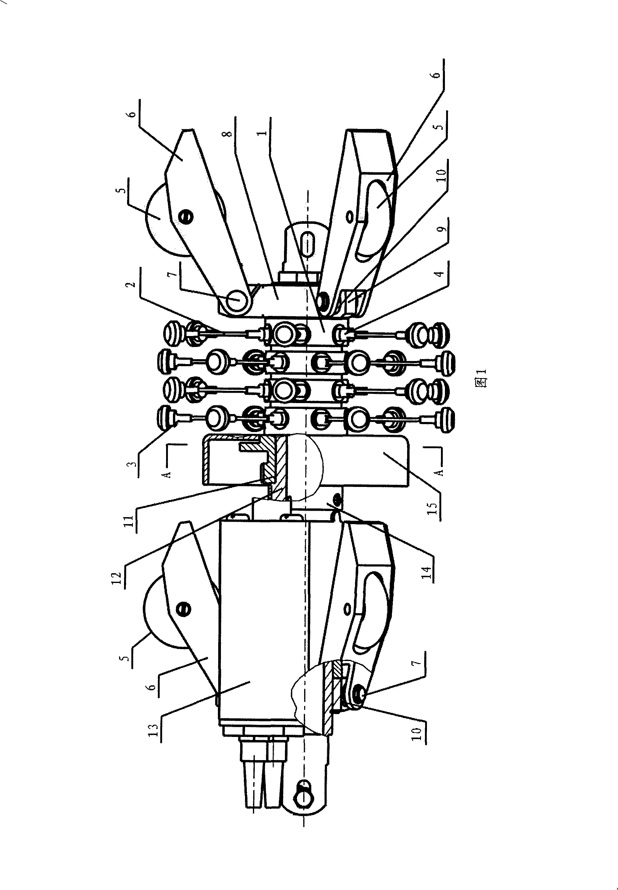
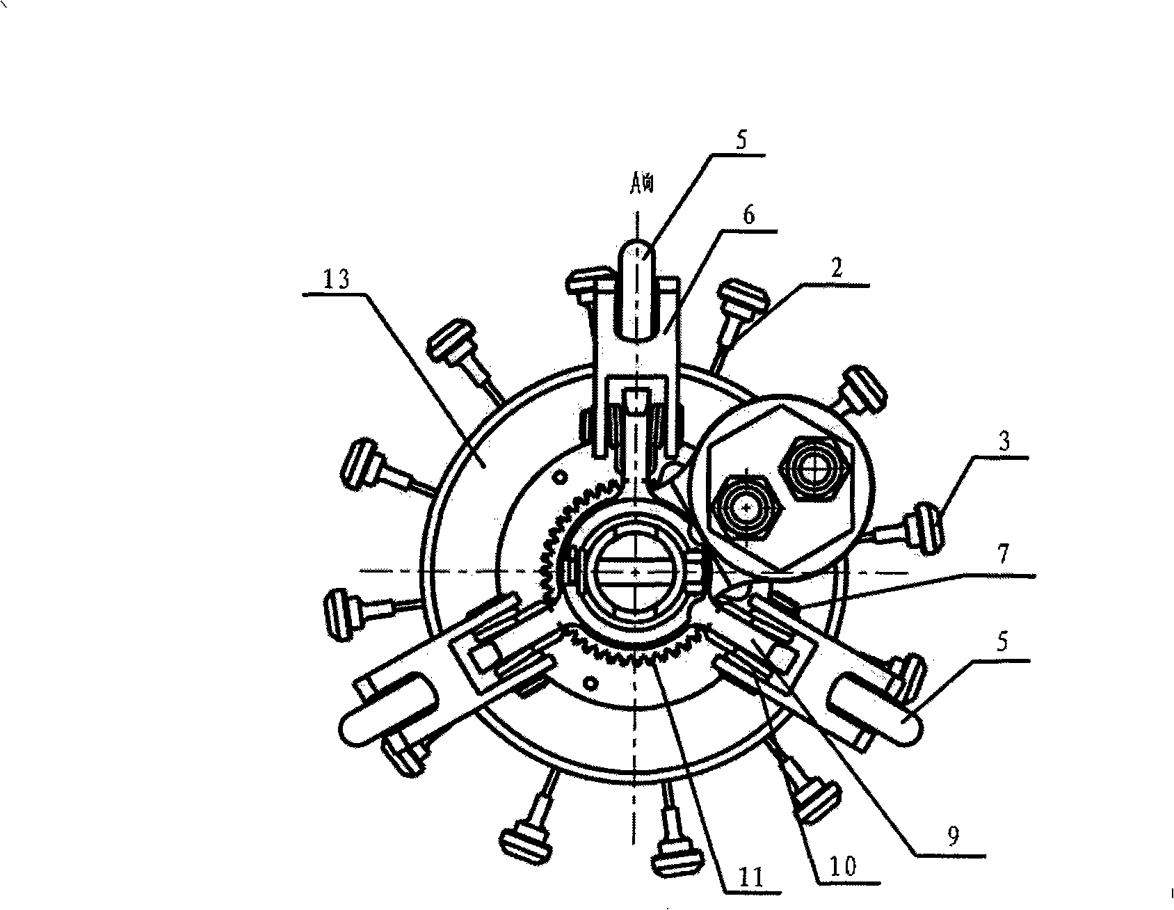
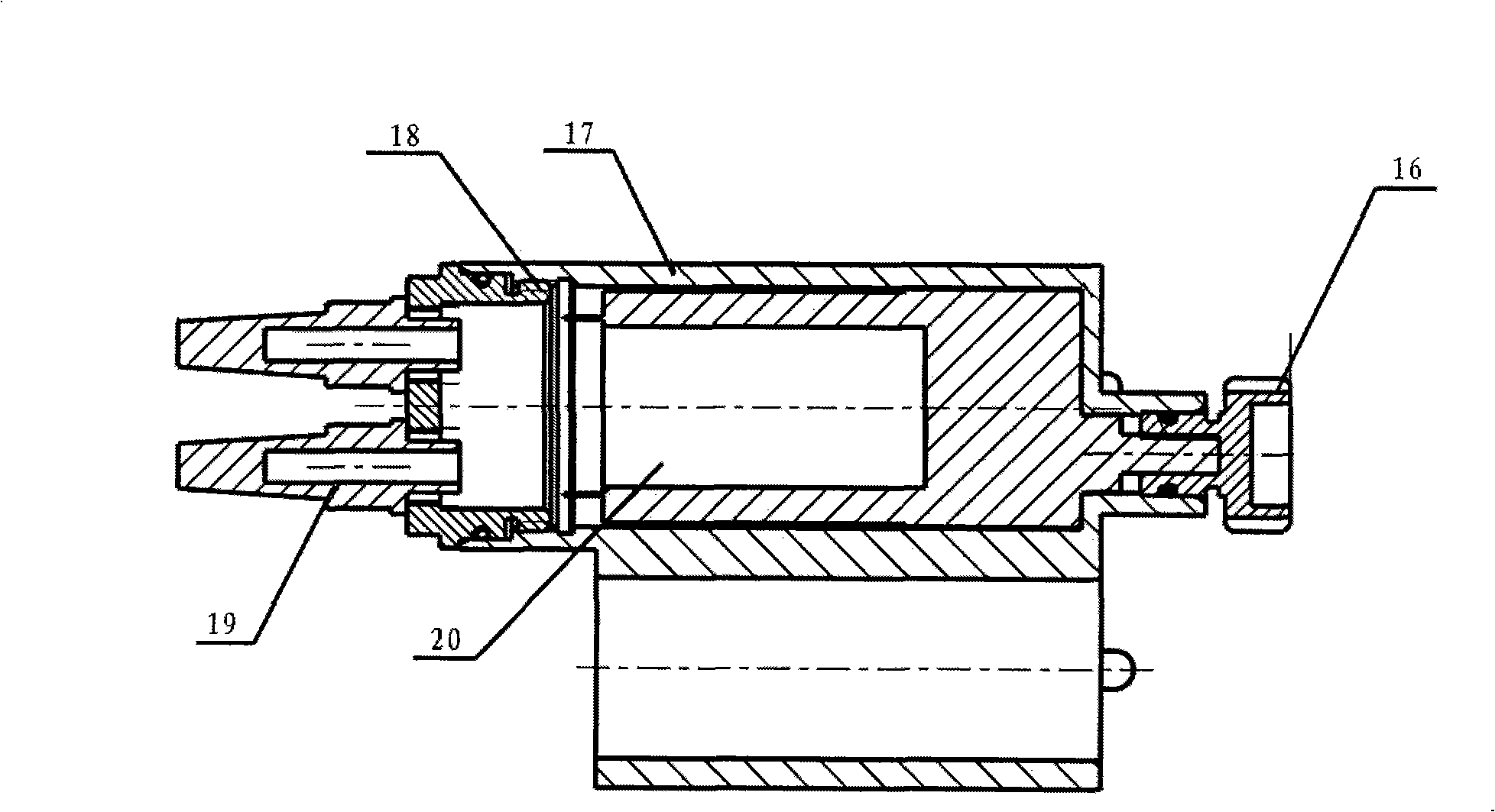
[0017] As shown in the figure: the sweeper includes a centerer, a sweeper and a drive mechanism 13 for driving the sweeper to rotate. In the sweeper mechanism, a number of flexible connecting arms 2 are arranged on the outer wall of the rotary body 1, and each The outer end of each connecting arm 2 is provided with a cleaning hammer 3, and the cleaning mechanism includes a rotary body 1, a connecting arm 2 and a cleaning hammer 3; Spring 10; the drive mechanism includes a motor and a transmission mechanism. When working, the motor 20 and the transmission mechanism make the flexible rotary hammer composed of the connecting arm 2 and the cleaning hammer 3 rotate. When the cleaning hammer 3 touches the concrete residue, the impact force generated by the stored kinetic energy of the flexible rotary hammer pushes the concrete residue from the inner wall of the pipeline. Peel and crush, while its flexible features keep the pipe cleaner from getting stuck in the pipe.

[0018] In th...


PUM


Abstract

The invention belongs to a power cable laying device, in particular to a clearing device for dredging the underground pipeline. According to the technique proposal provide by the invention, the clearing device for dredging the underground pipeline includes a center positioned device, a clearing device, and a driving mechanism that drives the clearing device to rotate. The invention is characterized in that a plurality of flexible connecting arms are arranged at the outer wall of a rotator in the clearing mechanism; a clearing hammer is arranged at the outer end of each connecting arm. The clearing hammer includes a tube part which is used to be connected with the tube shape connecting arm, and a head part with the function of collision. The head part is bigger than the tube part. The tube part is provided with a tube space for the connecting arm to insert in; and the outer end of the connecting arm is inserted in the tube space. The power cable laying device of the invention can expediently clear the inner wall of a pipeline, thus avoids the damage to the power cable by the thorn on the inner wall of the pipeline.

Description

technical field [0001] The invention belongs to equipment for laying power cables, in particular to a cleaner for dredging underground pipelines. Background technique [0002] The laying of power cables generally adopts the laying methods of pipe laying, tunnel laying, direct burial laying, underwater laying, and the combination of the above methods. Among them, trench laying, tunnel laying and underwater laying are mainly suitable for some special areas. At present, the most commonly used laying methods under urban roads are direct burial and piping. With the increase of investment in urban construction and the long-term planning of the city, direct burial laying will gradually be replaced by pipe laying methods with better applicability. [0003] Pipeline laying is an installation method of laying cables in pre-built underground pipelines. It is suitable for areas with relatively heavy urban traffic, crowded underground corridors, and a large number of laying lines. [0...

Claims


Application Information

Patent Timeline
Patent Type & Authority Applications(China)
IPC IPC(8): H02G1/06B08B9/04
Inventor 顾志强江秀臣吴寅雄曾奕勇明沈海平李立学
Owner WUXI POWER SUPPLY JIANGSU PROVINCE ELECTRIC POWER
Why Eureka
Try Eureka