
Air damper

A technology of air damping and lining, used in gas shock absorbers, shock absorbers, shock absorbers, etc.

Inactive Publication Date: 2008-11-26
ILLINOIS TOOL WORKS INC
View PDF0 Cites 6 Cited by
  • Summary
  • Abstract
  • Description
  • Claims
  • Application Information

AI Technical Summary

Problems solved by technology

Currently, few suppliers are capable of properly coating air dampers

Method used


Image

  • Air damper
  • Air damper
  • Air damper

Examples


Embodiment Construction

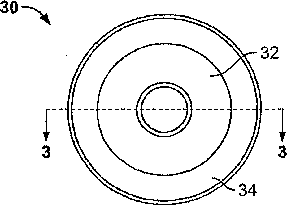
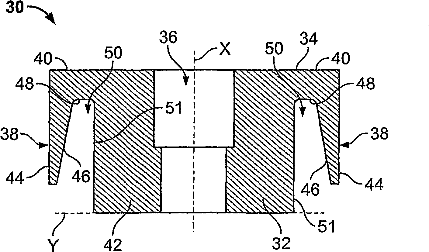
[0024] figure 2 A top plan view of a gasket cap (or piston tip) 30 according to one embodiment of the invention is illustrated. Gasket cap 30 includes a main cylinder or post 32 integrally connected to a circumferential ledge 34 extending around main cylinder 32 . Gasket cap 30 may or may not include holes (not shown) configured to control fluid leakage.

[0025] The liner cap 30 may be formed from a polyolefin, such as a resin-based polyolefin or a thermoplastic. Typically, polyolefin materials may contain oils or other fillers. Resins may, for example, be further classified as polyethylene or polypropylene from a group of materials. Such materials are further subdivided into Low Density Polyethylene (LDPE), Linear Low Density Polyethylene (LLDPE), Medium Density Polyethylene (MDPE), High Density Polyethylene (HDPE), High Molecular Weight Polyethylene and Ultra High Molecular Weight Polyethylene Polyethylene (HMWPE and UHMWPE), homopolypropylene, random copolymer polypro...


PUM


Abstract

An air damper (52) includes a main housing (54) having an interior wall defining an inner chamber (56), a piston (58) disposed within the inner chamber, and an arch-shaped gasket member (30) connected to the piston. The arch-shaped gasket member includes an annular rim (38) that sealingly engages the interior wall of the housing.

Description

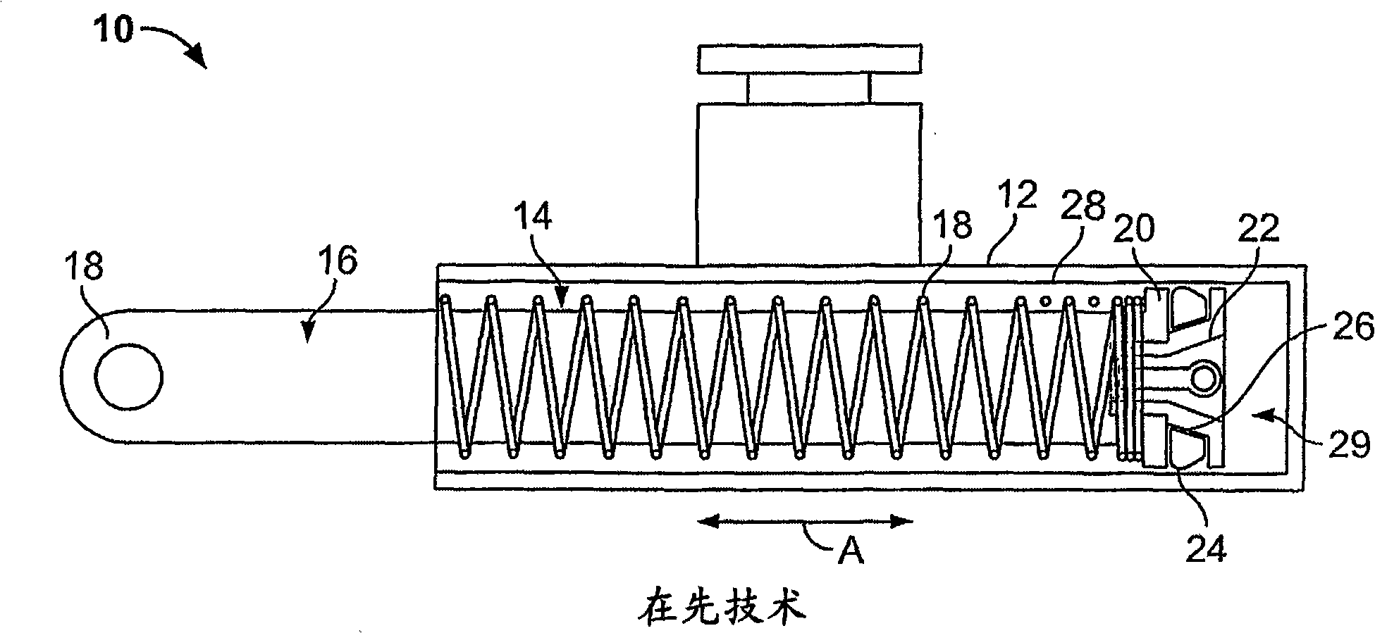
[0001] related application [0002] This application relates to and claims the benefit of priority to U.S. Provisional Patent Application No. 60 / 750,481, entitled "Air Damper," filed December 15, 2005, hereby, The Provisional Patent Application is incorporated by reference in its entirety. technical field [0003] Embodiments of the present invention generally relate to an air damper (Air Damper), and more particularly to an air damper that can be used in various automotive applications, such as an air damper with an automotive glove box (automobile glove box) device. Background technique [0004] figure 1 A side view of a conventional air damper 10 is illustrated. The air damper 10 includes a tubular housing 12 having an interior chamber 14 . Piston 16 is positioned within inner chamber 14 . Piston 16 includes a structurally engaging end 18 that extends outwardly from interior chamber 14 , and an end 20 within interior chamber 14 of housing 12 . To dampen movement of ...

Claims


Application Information

Patent Timeline
Patent Type & Authority Applications(China)
IPC IPC(8): F16F9/36F16F9/02
Inventor 简·托奇基欧文·J.·麦加勒尔雅斯曼·科奇
Owner ILLINOIS TOOL WORKS INC
Learn More