
Eureka
For R&D, Eureka makes reading and utilizing patents & technical documents easy.
Eureka AIR
Designed for self-driven R&D workflows. Generate viable solutions, solve complex R&D challenges, empower your innovation with AI.

Eureka Materials
Designed for material experts only. Revolutionize your material R&D, from search, analyze, to developing new materials.

TechResearch
Generate reliable direction feasibility study reports for your R&D in just a few steps.

TechSeek
Discover and master advanced knowledge NOW. Basics, ideas, possibilities, all at once.

TechMind
As an expert in R&D Theories, TechMind can generates customized viable solutions instantly.

TechRisk
Analyze your overall solution with one click, know your potential R&D risks in advance.

TechMonitor
Get weekly tech updates, stay abreast of the latest tech innovations and key insights.
Device for discharging plastic melt
A technology for plastics and melts, applied in the field of devices for discharging plastic melts, can solve problems such as harmfulness, and achieve the effects of reducing heat dissipation, reducing operating costs, and improving suction efficiency
- Summary
- Abstract
- Description
- Claims
- Application Information
AI Technical Summary
Problems solved by technology
Method used
Image

Examples
Embodiment Construction
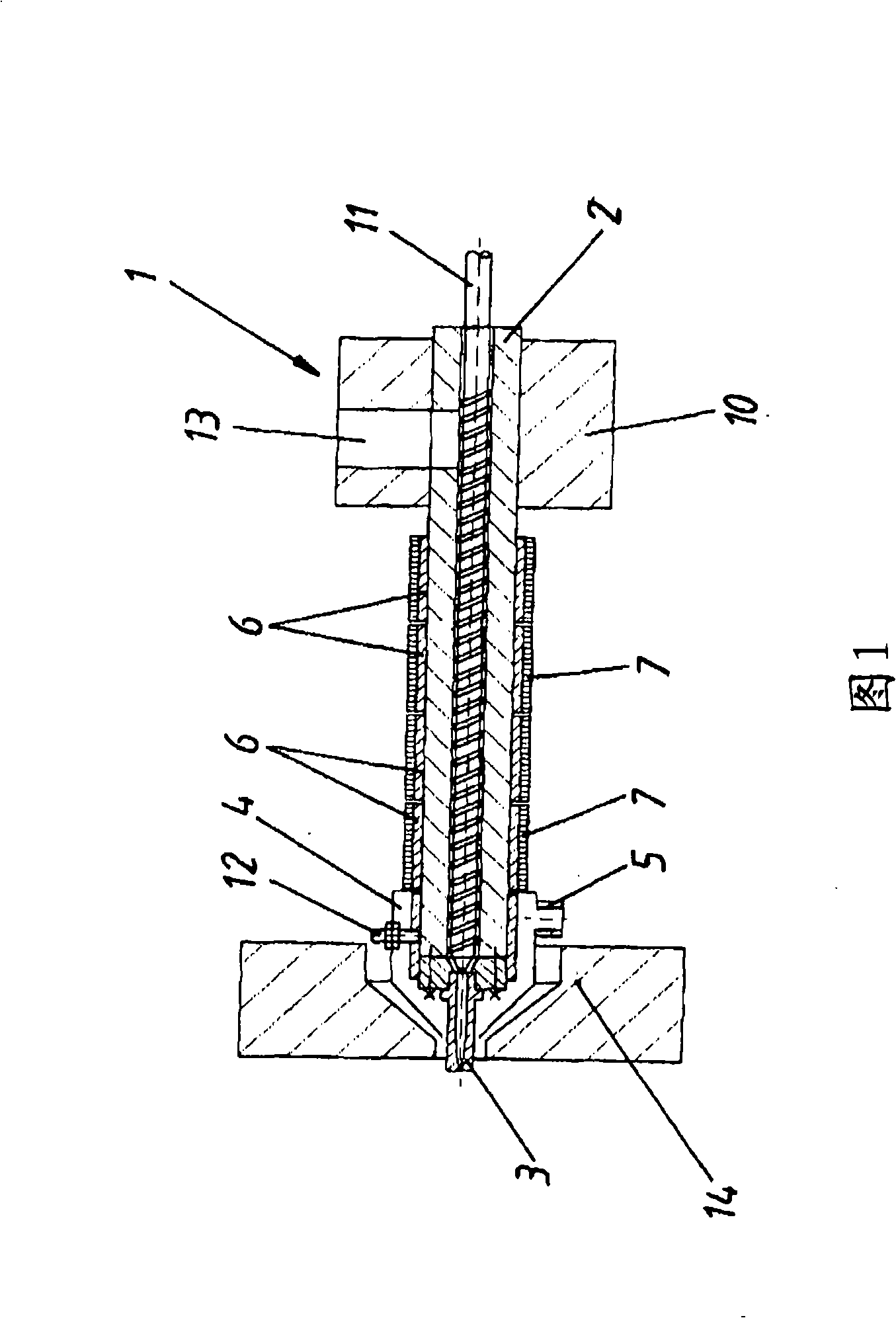
[0018] FIG. 1 shows a cross-sectional view of a first embodiment of a device 1 according to the invention.
[0019] In this exemplary embodiment, the device 1 is designed as an injector of an injection molding machine, not shown in detail, and therefore has a screw 11 mounted rotatably and axially displaceably in the cartridge 2 for plasticizing the plastic. The plastic melt produced by the plasticization collects in the known manner in the region of the screw tip, the escape of the plastic melt from the nozzle 3 being prevented by a non-illustrated stop before the injection process begins. For heating the plastic melt, in the exemplary embodiment four heating elements 6 are provided which are designed as heating strips and extend annularly around the outer surface of the cartridge 2 . The heating element 6 is insulated by an additional insulator 7 .
[0020] The housing 4 has a suction opening 5 which can be connected directly to a suction device, also not shown, or via a ho...
PUM
 Abstract
Description
Claims
Application Information
 - R&D Engineer
- R&D Manager
- IP Professional
- Industry Leading Data Capabilities
- Powerful AI technology
- Patent DNA Extraction
Browse by: Latest US Patents, China's latest patents, Technical Efficacy Thesaurus, Application Domain, Technology Topic, Popular Technical Reports.
© 2024 PatSnap. All rights reserved.Legal|Privacy policy|Modern Slavery Act Transparency Statement|Sitemap|About US| Contact US: help@patsnap.com