Image forming apparatus

A technology for image and printing operations, applied in image communication, electrical recording technology using charge patterns, equipment for electrical recording technology applying charge patterns, etc. Interleaving and other problems, to achieve the effect of improving convenience

Inactive Publication Date: 2012-06-20
KYOCERA DOCUMENT SOLUTIONS INC
View PDF1 Cites 0 Cited by
  • Summary
  • Abstract
  • Description
  • Claims
  • Application Information

AI Technical Summary

Problems solved by technology

[0005] However, in the above-mentioned conventional job management technology, for example, when the image forming apparatus performs print output based on a plurality of instructions received via a network from each user terminal and outputs the output products of each user related to a plurality of print jobs, When outputting to a common output tray, it may cause the output of each user to be interleaved and mixed together
In addition, this time may cause a user to mistakenly take someone else's output
In this case, if the output taken away by others involves confidential content, it is likely to cause unexpected troubles that cannot be ignored

Method used


Image

  • Image forming apparatus
  • Image forming apparatus
  • Image forming apparatus

Examples


no. 1 example

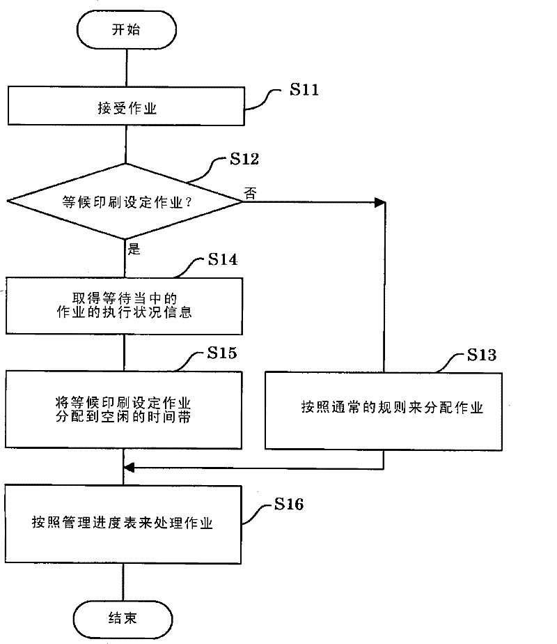
[0026] First, refer to figure 1 The first image forming apparatus 10 of the first embodiment will be described.

[0027] (Frame configuration around the first image forming device 10)

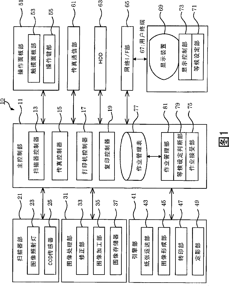
[0028] Such as figure 1 As shown, the first image forming apparatus 10 of the first embodiment can utilize various functions including a copying job, a fax sending and receiving job, a scanner job, a printing job, or a data communication job, and the first image forming apparatus 10 is controlled by the host. The main control unit 11 is controlled, and the main control unit 11 includes a microcomputer, a dedicated hardware circuit, and the like. As an input / output device connected to the main control unit 11 and responsible for various functions, the present image forming apparatus includes a scanner unit 21, an image processing unit 31, an engine unit 41, an operation panel unit 51, a facsimile communication unit 61, an HDD ( hard disk drive) 63, and a network I / F (interface) section 65.

...

no. 2 example

[0054] Next, refer to Figure 3 ~ Figure 5 The second image forming apparatus 20 of the second embodiment will be described. The above-mentioned first image forming apparatus 10 and the second image forming apparatus 20 described below have basically the same configurations of functional parts. Therefore, the same reference numerals are assigned to the same functional parts of the first and second image forming apparatuses 10 and 20 , overlapping descriptions are omitted, and only the differences between the two are emphasized.

[0055] (Frame configuration around the second image forming device 20)

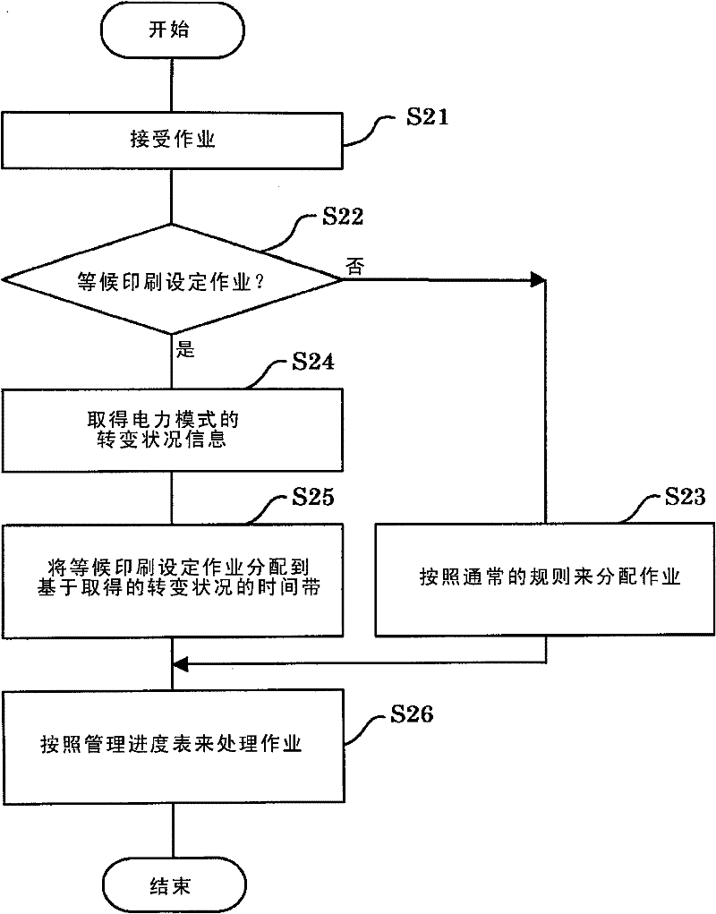
[0056] Such as Figure 4 As shown, the second image forming apparatus 20 further includes a power mode control unit 83 described below in addition to the configuration of the first image forming apparatus 10 described above.

[0057] That is, when a print job related to the waiting setting is received from the user terminal 67, in order to avoid as much as possible the output ...


PUM


Abstract

The present invention provides an image forming device, in the image forming device, a job managing section (81) acquires an operational status of a standby print job when a determination that a job having been accepted by a job accepting section (79) is a reserved low-key print setting job is made, as a result of a determination by a reserved setting determining section (75), and also allocates a printout for the reserved low-key print setting job to an available time slot based on the acquired operational status. As a result, the printout for the reserved low-key print setting job can be executed in an available time slot which is different from a time slot for the standby print job. Accordingly, mixing of printed sheets related to a plurality of print jobs can be prevented as much as possible, and a contribution to an improvement in convenience at the user-side can be made.

Description

technical field [0001] The present invention relates to an image forming apparatus equipped with a job management function, and in particular, to an image forming apparatus capable of avoiding output products of a plurality of print jobs from interlacing as much as possible, thereby significantly improving user convenience. Background technique [0002] Conventionally, there is known an image forming apparatus that has a job management function, that is, is connected to a plurality of information processing apparatuses (hereinafter, sometimes referred to as user terminals) owned by each user via a network, and receives printing from each user terminal. job, and executes the received print job as the management target in a predetermined order (for example, refer to Japanese Patent Laid-Open No. 2006-25137). [0003] An image forming apparatus applying the above prior art includes: a paper type information acquiring unit; a judging unit that judges whether a currently loaded t...

Claims


Application Information

Patent Timeline
Patent Type & Authority Patents(China)
IPC IPC(8): H04N1/00G03G15/00G03G21/00
Inventor 福田直记
Owner KYOCERA DOCUMENT SOLUTIONS INC
Why Eureka
Try Eureka