Liquid crystal display device and driving method thereof

A technology of a liquid crystal display device and a driving method, which is applied to static indicators, instruments, etc., can solve problems such as crosstalk interference of display devices, and achieve the effects of improving display quality and improving crosstalk interference

Inactive Publication Date: 2008-12-31
INNOCOM TECH (SHENZHEN) CO LTD +1
View PDF0 Cites 8 Cited by
  • Summary
  • Abstract
  • Description
  • Claims
  • Application Information

AI Technical Summary

Problems solved by technology

[0009] In order to solve the problem of crosstalk interference in liquid crystal display devices in the prior art, the present invention provides a liquid crystal display device that improves crosstalk interference

Method used


Image

  • Liquid crystal display device and driving method thereof
  • Liquid crystal display device and driving method thereof
  • Liquid crystal display device and driving method thereof

Examples


Embodiment Construction

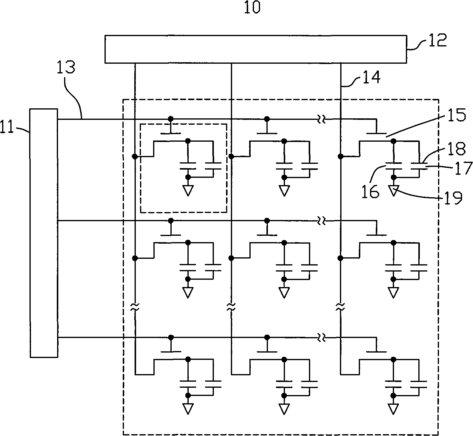
[0021] see Figure 4 , is a schematic structural view of the first embodiment of the liquid crystal display device of the present invention. The liquid crystal display device 20 includes a printed circuit board (PCB) 21 , a liquid crystal panel 22 and a plurality of flexible printed circuit boards (FPCB) 23 . The printed circuit board 21 is electrically connected to the liquid crystal panel 22 through the flexible printed circuit board 23 .

[0022] Each flexible printed circuit board 23 includes a data driving circuit 25 and a plurality of data lines 26 arranged on the surface of the flexible printed circuit board 23 . The data driving circuit 25 is electrically connected to the liquid crystal panel 22 through the data line 26 to drive the liquid crystal panel 22 to display images.

[0023] The printed circuit board 21 includes a common voltage generator 24 for providing a common voltage to the liquid crystal panel 22 . The common voltage generator 24 is respectively elect...


PUM


Abstract

The invention relates to a liquid crystal display device and a driving method thereof. The liquid crystal display device comprises a public voltage generator and a plurality of soft printing circuit boards; the soft printing circuit board comprises a plurality of data lines which are electrically connected with the public voltage generator; the data signals of a plurality of data lines are transmitted to the public voltage generator which adjusts the public voltage of the liquid crystal display device according to the voltage changing value when the polarity of the data signal is reversed. The liquid crystal display device can effectively improve the crosstalk interference and improve the display picture quality.

Description

technical field [0001] The invention relates to a liquid crystal display device and a driving method thereof. Background technique [0002] Liquid crystal display devices are widely used in electronic display devices such as mobile phones, televisions, and notebook computers due to their characteristics of low radiation and thin thickness. [0003] see figure 1 , is a structural schematic diagram of a prior art liquid crystal display device. The liquid crystal display device 10 includes a scanning driving circuit 11, a data driving circuit 12, a plurality of scanning lines 13 parallel to each other, a plurality of data lines 14 parallel to each other and perpendicularly intersecting with the scanning lines 13, and a plurality of data lines 14 located at the The pixel unit (not shown) at the intersection of the scan line 13 and the data line 14, wherein three adjacent RGB pixel units form a pixel (not shown). The scan driving circuit 11 is used for driving the scan lines 1...

Claims


Application Information

Patent Timeline
Patent Type & Authority Applications(China)
IPC IPC(8): G02F1/133G09G3/36
CPCG09G3/3655
Inventor 卓圣田
Owner INNOCOM TECH (SHENZHEN) CO LTD
Why Eureka
Try Eureka