
Coupling terminal structure of electrical connector and electrical connector

An electrical connector and terminal structure technology, which is applied to the components, connections, coupling devices and other directions of connection devices, can solve problems such as terminal crosstalk interference, and achieve the effects of reducing interference, improving signal transmission quality, and improving crosstalk interference.

Active Publication Date: 2016-05-18
STARCONN ELECTRONICS SU ZHOU CO LTD
View PDF6 Cites 0 Cited by
  • Summary
  • Abstract
  • Description
  • Claims
  • Application Information

AI Technical Summary

Problems solved by technology

[0006] The main purpose of the present invention is to provide a coupling terminal structure of an electrical connector, to improve the problem of crosstalk interference between terminals, and to improve signal transmission quality

Method used


Image

  • Coupling terminal structure of electrical connector and electrical connector
  • Coupling terminal structure of electrical connector and electrical connector
  • Coupling terminal structure of electrical connector and electrical connector

Examples


Embodiment Construction

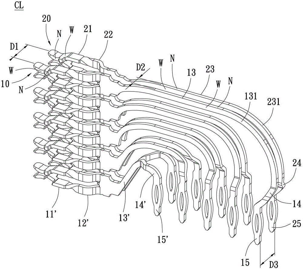
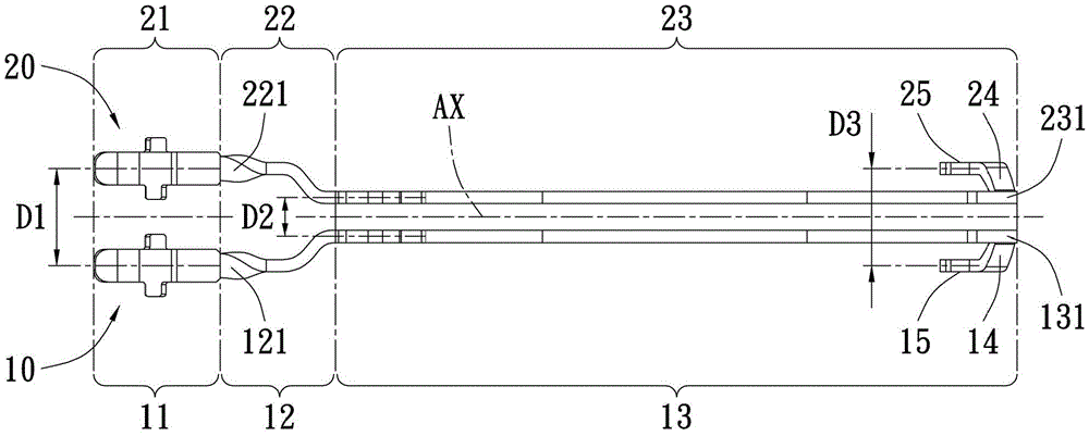
[0073] see figure 2 , image 3 , Figure 4 As shown, in order to improve the crosstalk interference between the electrical transmission terminal and other electrical transmission terminals, or the internal crosstalk of the electrical transmission terminal itself, the present invention provides a coupling terminal structure of an electrical connector, which is used for In order to generate electromagnetic coupling effects with each other when transmitting electrical signals, and to reduce crosstalk interference through a non-grounded shielding structure, the above two terminals are used as an example to illustrate, which includes: an array paired first terminal 10 and a second terminal terminals 20, and are juxtaposed with each other to form a three-dimensional terminal cluster CL, figure 2Shown is a 2x5 terminal cluster CL, but it is not limited thereto. The terminal cluster CL can also be 4x5, 6x5 or 4x8, etc. The first terminal 10 and the second terminal 20 can be any ty...


PUM


Abstract

The invention provides a coupling terminal structure of an electric connector and the electric connector thereof. The coupling terminal structure of the electric connector comprises a first terminal and a second terminal in pair at least, wherein the first terminal comprises a first touch end, a first neck and a first extending part successively from one end. The second terminal comprises a second touch end which corresponds with the first touch end, a second neck which corresponds with the first neck, and a second extending part which corresponds with the first extending part successively from one end. The first touch end is separated from the second touch end for a first distance. The first extending part is separated from the second extending part for a second distance. The first distance is larger than the second distance. Therefore an electromagnetic coupling effect is generated between the first extending part and the second extending part, so that better coating performance can be realized on the transmitted signal, thereby reducing outwards and self interference.

Description

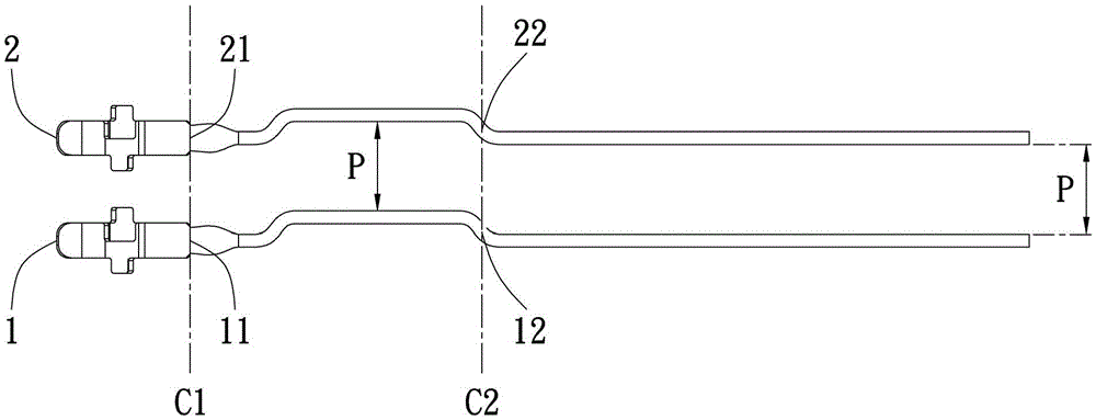
technical field [0001] The invention relates to a coupling terminal structure of an electrical connector and an electrical connector, in particular to a coupling terminal structure and an electrical connection of an electrical connector that utilizes structural characteristics between terminals to generate an electromagnetic coupling effect to improve crosstalk interference. device. Background technique [0002] The structure of the coupling terminal of the existing electrical connector is as follows: figure 1 As shown, the first terminal 1 and the second terminal 2 are substantially in the same style and structure, and the parts of the two are substantially parallel to each other from the beginning to the end. Therefore, for example, assuming that there is a first crosscutting line C1 that cuts two first crosscutting points (11, 21) at the left ends of the first terminal 1 and the second terminal 2 that are arranged side by side and have the same structure, the two first ...

Claims


Application Information

Patent Timeline
Patent Type & Authority Patents(China)
IPC IPC(8): H01R13/646H01R13/02
Inventor 包中南林钰雄黄圣翔柯宇丰
Owner STARCONN ELECTRONICS SU ZHOU CO LTD
Learn More