Push structure of forming device lower knife

A technology for cold-formed forming machines and rolling parts, applied in forming tools, metal processing equipment, manufacturing tools, etc., can solve the problem that the lower tool seat plate has a large impact on the machine tool, the stability and reliability of the forming machine are not high, and the frictional resistance is small. and other problems, to achieve the effect of high stability and reliability

Active Publication Date: 2011-07-20
SUZHOU JINTONG MACHINERY MFG
View PDF0 Cites 0 Cited by
  • Summary
  • Abstract
  • Description
  • Claims
  • Application Information

AI Technical Summary

Problems solved by technology

[0002] In the pushing structure of the lower knife of the cold roll forming machine, the moving box reciprocates back and forth in the horizontal plane, and drives the lower knife seat plate to reciprocate in the vertical direction. The lower knife seat is installed on the lower knife seat plate, and the moving box Both the top of the top and the bottom of the lower knife seat plate have guide slopes. The guide slopes of the moving box are rotatably provided with a plurality of rolling parts for reducing friction. The rolling parts contact the guide slopes of the lower knife seat plate and roll. , through the action of the guide slope, the force in the horizontal direction of the moving box is changed to the force in the vertical direction of the lower knife seat plate, and there is rolling friction between the two guide slopes, and the friction resistance is very small. On the cold roll forming machine, The reciprocating motion of the moving box in the horizontal plane is driven by the oil cylinder. There is a return spring between the lower knife seat plate and the machine tool. position, the moving box is separated from the lower tool seat plate, and the lower tool seat plate has a hysteresis effect when returning to its position under its own gravity. Although there is a return spring, the impact of the lower tool seat plate on the machine tool is still large, causing Great vibration, huge noise, low stability and reliability of the molding machine

Method used


Image

  • Push structure of forming device lower knife
  • Push structure of forming device lower knife
  • Push structure of forming device lower knife

Examples


Embodiment Construction

[0009] The specific structure and working principle of the present invention will be further described below in conjunction with the accompanying drawings.

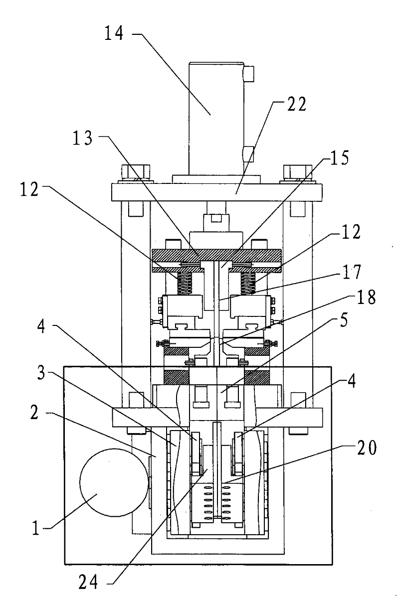
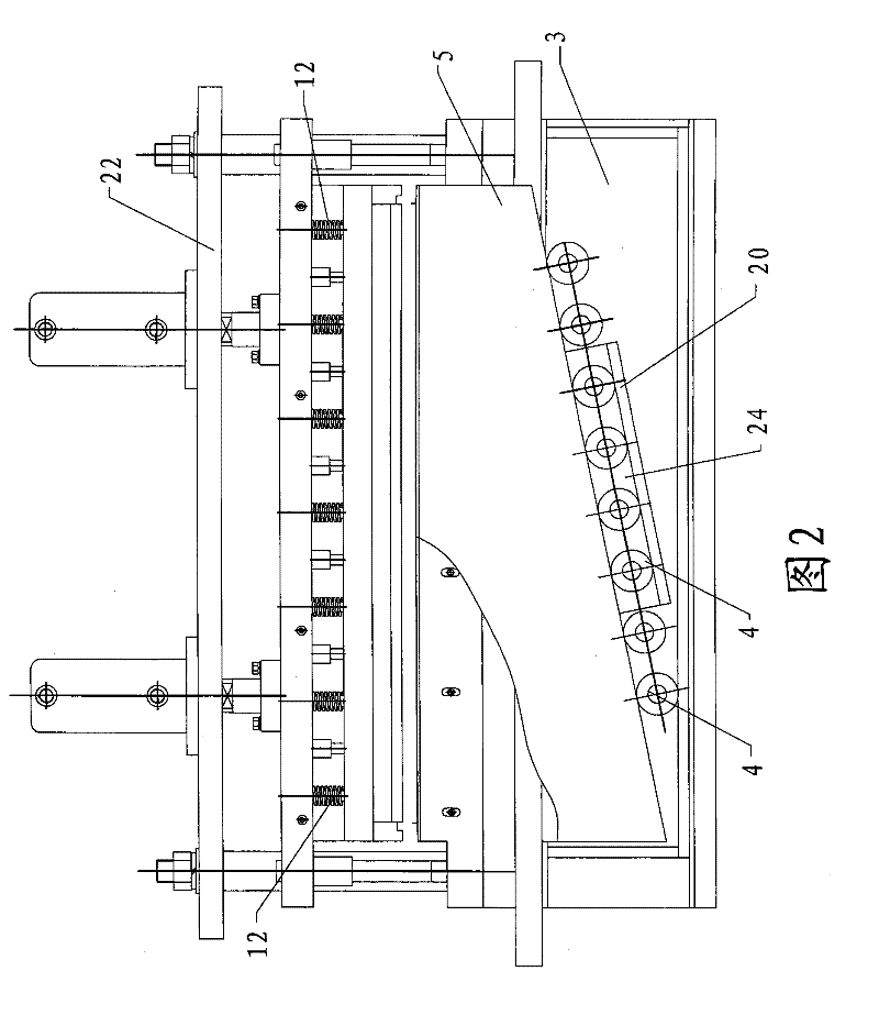
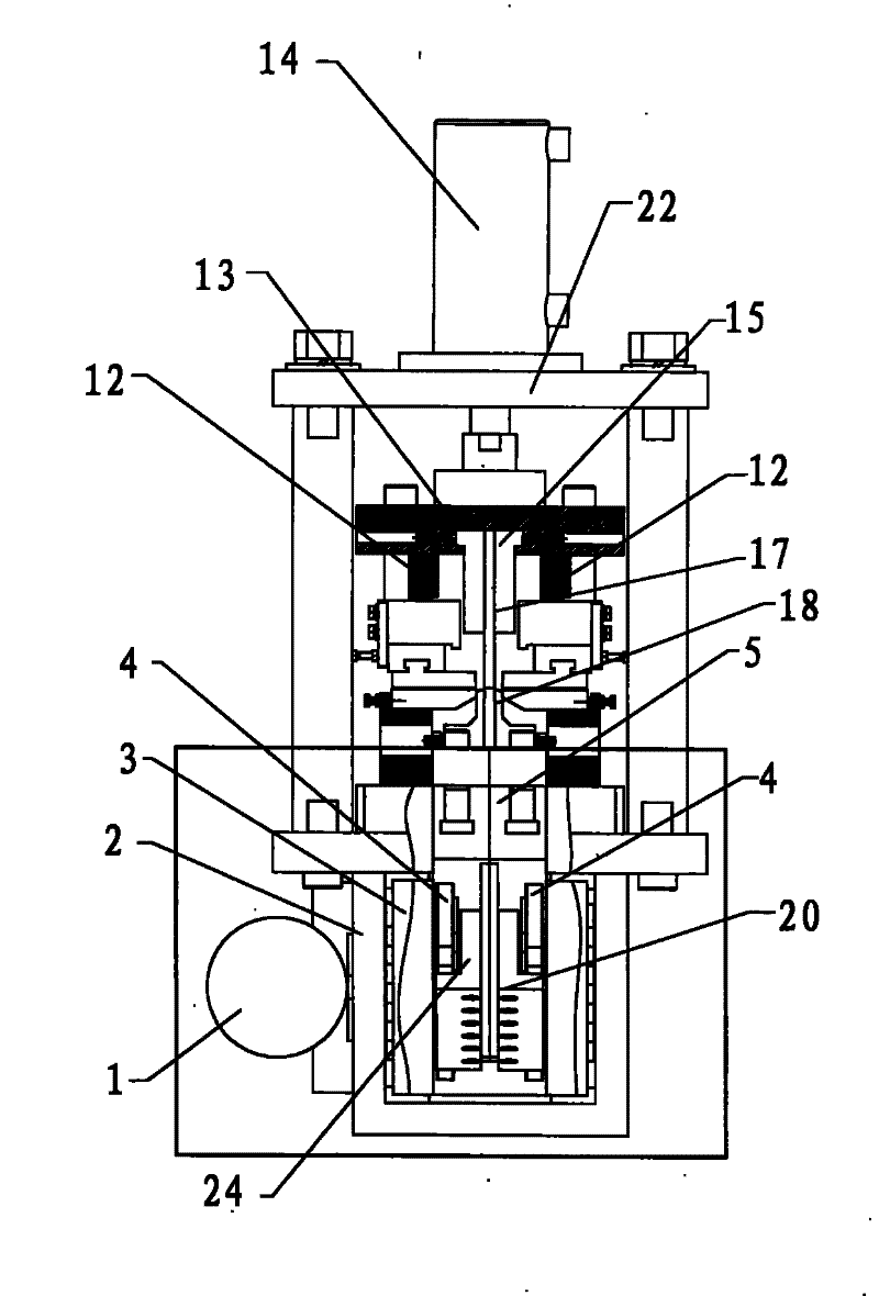
[0010] See attached figure 1 As shown in and 2, a push structure for the lower knife of a cold roll forming machine is used to control the upward shearing and downward return of the lower knife, including a moving box 3 that moves back and forth in the horizontal plane, and in the vertical direction The lower knife seat plate 5 that moves back and forth and is driven by the moving box 3, the top of the moving box 3 and the bottom of the lower knife seat plate 5 have guide slopes, the lower knife A lower knife 18 is installed on the seat plate 5, and a plurality of rolling elements 4 for reducing friction are rotatably provided on the guide slope of the moving box 3, at least part of the rolling elements 4 and the guide of the lower knife seat plate 5 The inclined surfaces are in contact with each other, and rolling occur...


PUM


Abstract

The invention discloses a push structure for a lower tool of a cold-bending forming machine. Guide inclined surfaces are arranged on the top of a mobile box body and at the bottom of a lower tool base plate in the push structure; a plurality of rolling elements used for reducing the friction are rotationally arranged on the guide inclined surface of the mobile box body; the rolling elements are in contact with the guide inclined surface of the lower tool base plate, so as to roll; a passage is arranged at the bottom of the lower tool base plate, and at least some of the rolling elements pass through the passage; when the mobile box body drives the lower tool base plate to move upwards, the rolling elements are propped against the top wall of the passage; the top wall of the passage forms the guide inclined surface of the lower tool base plate; under the action of the guide inclined surfaces, the mobile box body pushes the lower tool base plate to lead the lower tool to shear upwards; when the lower tool base plate is returned, the rolling elements are propped against the bottom wall of the passage, so that the mobile box body drives the lower tool base plate to move downwards and return; because of the buffer of the mobile box body, the lower tool base plate can lead the lower tool to return smoothly, and the impact on a machine tool is very small; therefore, the forming machine has the advantages of high stability and reliability.

Description

technical field [0001] The invention relates to a pushing structure for a lower knife of a metal thin plate cold bending forming machine. Background technique [0002] In the pushing structure of the lower knife of the cold roll forming machine, the moving box reciprocates back and forth in the horizontal plane, and drives the lower knife seat plate to reciprocate in the vertical direction. The lower knife seat is installed on the lower knife seat plate, and the moving box Both the top of the top and the bottom of the lower knife seat plate have guide slopes. The guide slopes of the moving box are rotatably provided with a plurality of rolling parts for reducing friction. The rolling parts contact the guide slopes of the lower knife seat plate and roll. , through the action of the guide slope, the force in the horizontal direction of the moving box is changed to the force in the vertical direction of the lower knife seat plate, and there is rolling friction between the two g...

Claims


Application Information

Patent Timeline
Patent Type & Authority Patents(China)
IPC IPC(8): B21D5/00B21D37/00
Inventor 蒋明生
Owner SUZHOU JINTONG MACHINERY MFG
Why Eureka
Try Eureka