
Heat transfer pipe for condensation

A technology of heat transfer tube and heat exchange area, which is applied in heat transfer modification, tubular elements, heat exchange equipment, etc., can solve the problem that heat exchange efficiency cannot be further improved, and achieve the effect of improving heat exchange performance.

Inactive Publication Date: 2011-05-04
WOLVERINE TUBE (SHANGHAI) CO LTD
View PDF9 Cites 0 Cited by
  • Summary
  • Abstract
  • Description
  • Claims
  • Application Information

AI Technical Summary

Problems solved by technology

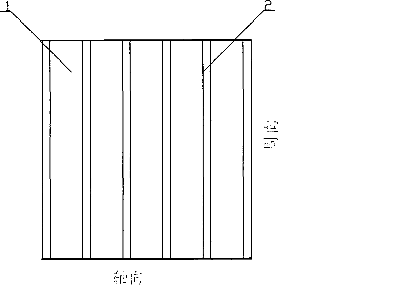
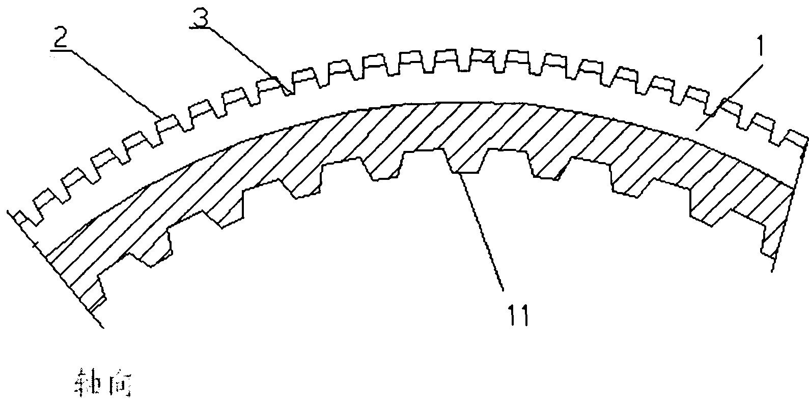
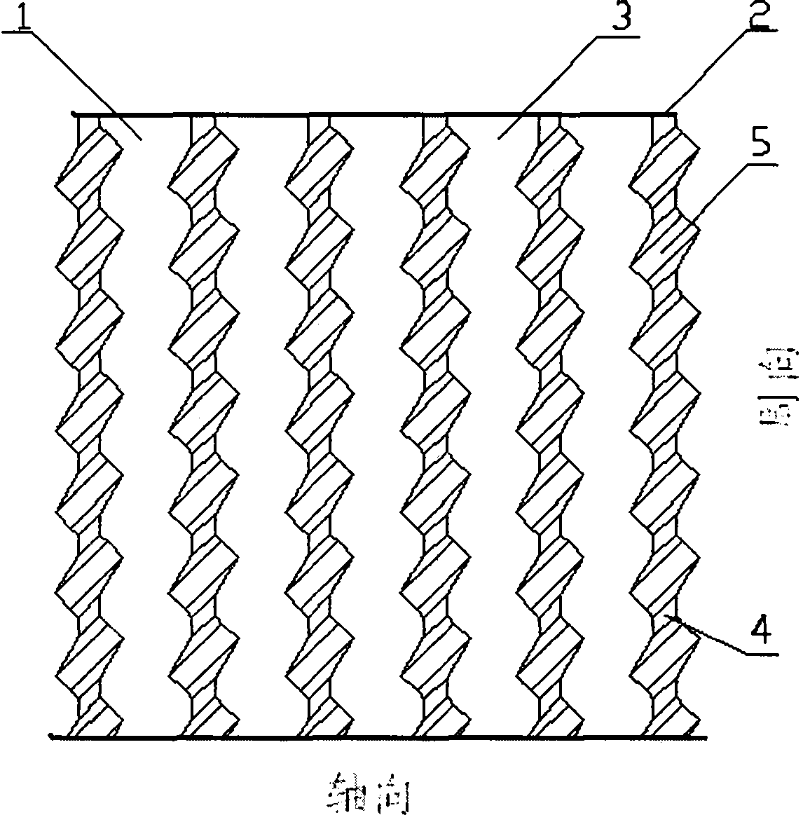
[0003] Generally, people make such heat transfer tubes as, for example, figure 1 , figure 2 , image 3 As shown in Fig. 1, ring-shaped fins are pressed on the outer surface of the heat transfer tube, and then fin grooves are pressed on the fins to form a fin table, which increases the heat transfer area to a certain extent, but still cannot further improve the heat transfer efficiency.

Method used


Image

  • Heat transfer pipe for condensation
  • Heat transfer pipe for condensation
  • Heat transfer pipe for condensation

Examples


Embodiment Construction

[0030] In order to make the technical means, creative features, goals and effects achieved by the present invention easy to understand, the present invention will be further described below in conjunction with specific illustrations.

[0031] The heat transfer tube in the prior art adopts the method of double-sided enhanced heat transfer, and its structure is as follows: figure 1 , figure 2 , image 3 , Figure 3a shown. Among them, the outer surface of the tube main body 1 is distributed with spiral or parallel fins 2 along the circumferential direction, and inter-fin grooves 3 are formed between the fins 2 along the circumferential direction; The fin platform 5 is formed; the heat transfer tube 1 has an internal thread 11 inside.

[0032] Embodiment 1 of the present invention, refer to Figure 4 , Figure 4a , on the basis of the existing heat transfer tubes, the L-shaped fin platform 6 is compounded by processing. The L-shaped fin platform 6 includes the upper fin pl...


PUM


Abstract

The invention provides a heat transfer pipe used for condensation. Fins which can increase the heat exchange area are pressed on the external surface of the heat transfer pipe. The heat transfer pipe is characterized in that two or more than two layers of fin platforms in composite structure are pressed on the fins; fin slots are arranged between the fin platforms; the fin platforms can be L-shaped, three-step-shaped, V-shaped, Y-shaped or in the shape with one square above and in the middle of the two squares. As the steps on the side walls of the fin platforms or the turning points multipled in number formed based on the slots on the top of the fin platforms through processing play a role in condensation and reinforcement of heat transfer, the heat exchange performance of the condensation side of the heat transfer pipe is improved by 6.5 to 15.0 percent compared with the prior art according to the test results by adopting R134a for condensation.

Description

technical field [0001] The invention belongs to the technical field of heat transfer equipment, and in particular relates to a heat transfer tube for condensation. Background technique [0002] In refrigeration and air conditioning and related industries, water-cooled condensers have been widely used. Most of them are shell and tube heat exchangers, in which the refrigerant condenses outside the tube to exchange heat, and the coolant (such as water) flows in the tube to exchange heat. Because the thermal resistance of the refrigerant side accounts for the main part, it is necessary to adopt enhanced heat transfer technology on this side. For the phase change heat transfer of condensation, there are many heat transfer tubes specially for this type of process: such as heat transfer for condensation enhanced surface The tube has US patent US5996686 and US patent US5669441. It forms fins on the outer surface of the tube by machining and knurling on the top of the wing. The main...

Claims


Application Information

Patent Timeline
Patent Type & Authority Patents(China)
IPC IPC(8): F28F1/02F28F1/36
CPCF28F1/36F28F1/42F28F1/422F28F13/187Y10T29/49364
Inventor 罗忠曹建英伍剑邱亚林
Owner WOLVERINE TUBE (SHANGHAI) CO LTD
Learn More