Rolling angle measurement method and device based on grating

A roll angle measurement and measurement device technology, applied in the direction of measuring devices, optical devices, instruments, etc., can solve the problem of demanding working environment, limited measurement sensitivity, degree of polarization, laser frequency stability, signal-to-noise ratio of signal amplifier circuit, and inability Real-time measurement and other issues, to achieve the effect of simple and compact optical structure, enhanced anti-interference ability, and convenient on-site measurement

Inactive Publication Date: 2010-04-07
BEIJING JIAOTONG UNIV
View PDF3 Cites 2 Cited by
  • Summary
  • Abstract
  • Description
  • Claims
  • Application Information

AI Technical Summary

Problems solved by technology

[0003] For the high-precision measurement of the roll angle of the guide rail, there are several optical methods as follows: 1. parallel double-beam method, [John C.Tsai.Rotation and translation measurement with phase sensitive detection, U.S. Patent No.: 6316779B1, 2001], by detecting two The roll angle error is obtained by calculating the change of different positions relative to the position of the parallel laser beam. The disadvantage is that the roll angle measurement is related to other parameters, and the parallelism of the beam is difficult to guarantee.
2. Polarization direction measurement method, including Faraday magneto-optical modulation method, [Fang Zhongping. Research on laser roll error measuring instrument, doctoral dissertation, Tianjin: Tianjin University, 1993], this method has optical thermal drift, and the measurement accuracy is not high. In order to improve the measurement accuracy, the feedback circuit is complex and the working environment is demanding
Although it is relatively simple in the optical path, the measurement moving part has cables, and the measurement sensitivity is not high
Quarter-wave plate method [Kuang Cuifang, Feng Qibo, Zhang Bin. A new roll angle measurement method, Optoelectronic Laser, 2006, 17(4): 468-470; Kuang Cuifang et al., based on quarter-wave plate rolling Rotation angle measurement method and device, Chinese Patent No.: 1687701A, 2005], although this method realizes the measurement of the moving part without cables, it still converts the roll angle error into the light intensity change of the outgoing light, and the measurement sensitivity is limited by the measurement light. Polarization degree, laser frequency stability and signal-to-noise ratio of signal amplification circuit, etc. If you want to improve the sensitivity, the economic cost will also increase greatly
3. Interferometric method, Chaney proposed a method to measure the roll angle using interference [Raymond J.Chaney. Optical apparatus for use with interferometric measuring device, U.S. Patent No.: 5056921, 1991], which can obtain high measurement accuracy, However, the measurement system needs to install a reflective plane mirror as long as the guide rail, which is difficult to apply in practice
Another interferometry is based on dual-frequency laser interferometry, which has the advantages of high precision and strong anti-interference ability, but it needs to measure the straightness of two different positions step by step to calculate the roll angle, which cannot be used for real-time measurement. Time-consuming and labor-intensive, this method is mainly used in machine tool testing at present

Method used


Image

  • Rolling angle measurement method and device based on grating
  • Rolling angle measurement method and device based on grating
  • Rolling angle measurement method and device based on grating

Examples


Embodiment Construction

[0018] The present invention will be further described below in conjunction with the accompanying drawings and specific embodiments.

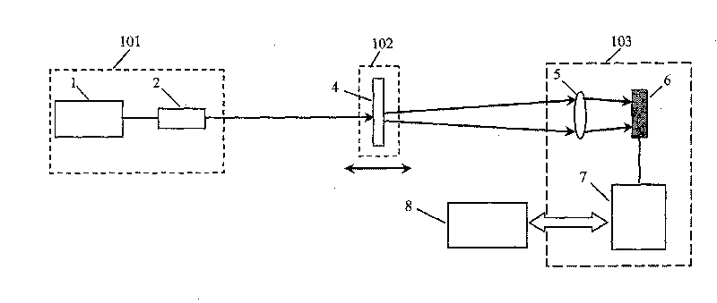
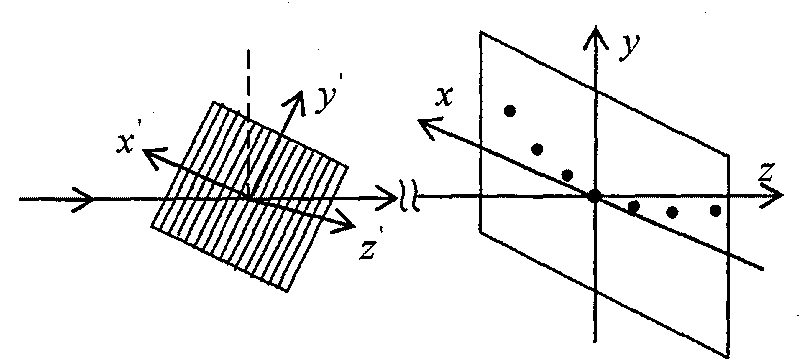
[0019] The method for measuring the roll angle based on the grating of the present invention is that the laser 1 emits laser light, which is collimated by the collimator lens 2 and then incident on the measurement platform. figure 1 After being reversed by the retroreflector 3 as shown, it passes through the grating 4, or as figure 2 As shown directly passes through the grating 4 to generate positive and negative first-order diffracted double beams. The above-mentioned laser 1 can be a He-Ne laser, a semiconductor laser or other types of lasers. The collimator lens 2 and the retroreflector 3 mentioned above can be selected according to the measurement requirements. The above-mentioned collimating lens 2 may be a single lens or a lens group. The above-mentioned retroreflector 3 may be a corner cube prism, a right-angle reflector or a cat's e...


PUM


Abstract

The invention discloses a roll angle measuring method based on a grating and a device thereof, which belongs to the technical field of photoelectric detection. A laser lases and emerges directly, or emerges after collimation through a collimating lens; the light is directly incident on a one-dimensional plane transmission grating, or reversely incident on the grating through a retrodirective reflector; plus-minus first stage diffracted light from the grating is focused to form two diffracted light points through a lens; a photodetector is used to detect the variations in positions of the two focused light points, thus figuring out a roll angle. The optical structure of the device is compact and simple, and brings convenience to practice; in addition, the accuracy, the stability and the economical efficiency are also high. The grating is used as a sensitive device; error separation is achieved, and the interference-free feature is improved by using the differential measurement of doublediffracted beams; few optical devices are used; and the power of the light source is low; the cost is low; mobile parts do not require to be provided with cables; the angle measurement distinguishability is as high as 0.5 and even higher; different requirements of measurement accuracy can be met just by replacing the grating with gratings having different numbers of lines.

Description

technical field [0001] The invention belongs to the technical field of photoelectric detection, and in particular relates to a non-contact method and device for measuring roll angle. Background technique [0002] The kinematic pairs of mechanical guide rails have three degrees of freedom of rotation or angular motion errors (pitch, yaw, and roll errors). If instruments and machine tools have Abbe arms in the direction corresponding to these angular motion errors, these angular motion errors will cause Abbe errors and affect their processing or measurement accuracy. At present, reducing or eliminating the Abbe error is mainly to reduce the Abbe arm from the structure, improve the motion accuracy and error correction of the guide rail according to Brain's suggestion, and reduce or eliminate the influence of the Abbe error from the structure according to Eppenstein's principle. Due to the limitation of mechanical structure and geometric size, almost all coordinate measuring ma...

Claims


Application Information

Patent Timeline
Patent Type & Authority Patents(China)
IPC IPC(8): G01B11/26
Inventor 冯其波翟玉生张斌
Owner BEIJING JIAOTONG UNIV
Why Eureka
Try Eureka