
Corrugated tube and installation method

A technology of bellows and locking protrusions, applied in the direction of hose connection devices, hoses, pipes, etc., can solve problems such as gripping of installation components

Inactive Publication Date: 2009-01-14
SUMITOMO WIRING SYST LTD
View PDF1 Cites 4 Cited by
  • Summary
  • Abstract
  • Description
  • Claims
  • Application Information

AI Technical Summary

Problems solved by technology

[0004] However, in the case of using a bellows while installing a mounting member such as a protector thereon, the above configuration has a problem that if an attempt is made to rotate the mounting member in the circumferential direction of the bellows, the mounting Components are easily gripped by ring-shaped locking notches

Method used


Image

  • Corrugated tube and installation method
  • Corrugated tube and installation method
  • Corrugated tube and installation method

Examples


Embodiment Construction

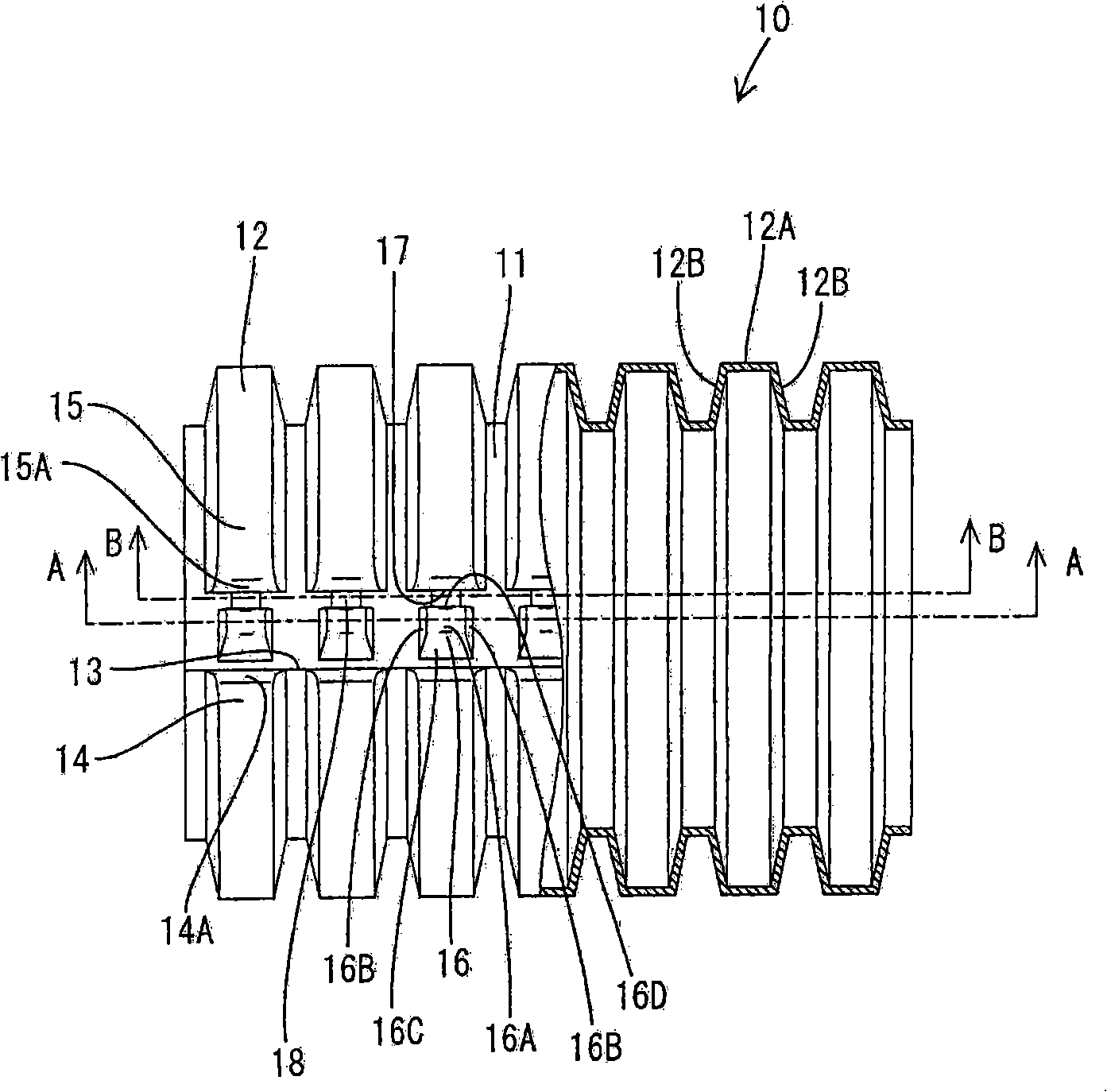
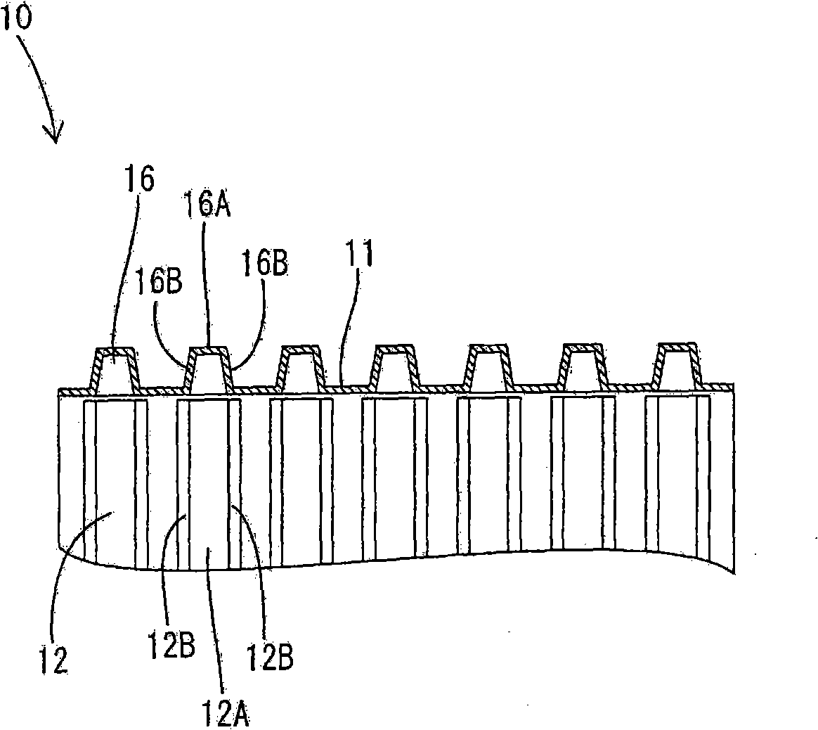
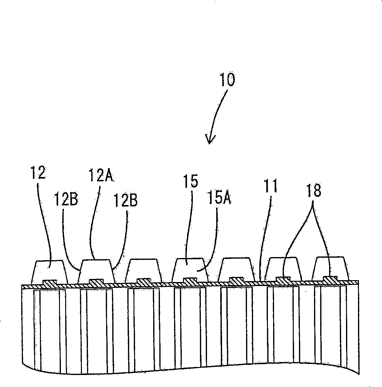
[0056] In the following, refer to the attached Figures 1 to 6 A preferred embodiment of the present invention is described.

[0057] The corrugated tube 10 in this embodiment is to be mounted to a specific (preset or pre-determinable) location of an unspecified wire group or to the wire group to protect the wire group by at least partially surrounding it. The bellows 10 is made of, for example, synthetic resin, and has a bellow or corrugated shape in which several substantially annular protrusions 12 emerge from (preferably substantially cylindrical) at specific (preset or predeterminable) intervals Shaped) the inner wall 11 protrudes and has such flexibility that it is preferably able to flexibly advance along the laying path of the wire group. The bellows 10 is formed with (preferably substantially straight) slits 13 over its entire length in its longitudinal direction.

[0058] The annular protrusion 12 extends circumferentially from a position in contact with the slit 1...


PUM


Abstract

The invention provides a corrugated tube, which prevents mounting components from capturing circumferentially even if having a locking structure. The corrugated tube has a slit (13) and first closing walls (14A) of circumferentially extending annular projections (12) are formed along the slit (13). Lock projections (16) dimensioned to be fitted inside the annular projections (12) are provided between the first closing walls (14A) and the other closing walls (15A). The lock projections (16) are tapered toward the projecting ends thereof and clearances, into which the first closing walls (14A) are insertable are defined between the lock projections (16) and the other closing walls (15A). Out of the opposite ends (14, 15) of the annular projections (12), the ends corresponding to the first closing walls (14A) are fitted on the lock projections (16) to engage the first closing walls (14A) and the lock projections (16), thereby locking the slit (13) in a closed state.

Description

technical field [0001] The invention relates to a corrugated pipe provided with a locking structure and an installation method thereof. Background technique [0002] A bellows formed with a longitudinal slit is known as a bellows installed at a specific position of the wire group. By opening the slits, the bellows can be fitted sideways at specific positions on the wire group. However, when such a corrugated tube is used, the slit is opened when the wire group is bent, so that bundling or the like is required. [0003] Therefore, there is known a bellows provided with a locking structure capable of locking the slit into a closed state so that such a binding operation is unnecessary (for example, Japanese Unexamined Patent Publication No. H10-136531). The bellows is constructed so as to lock the bellows by forming mutually engageable locking notches at opposite ends (opposite ends facing at opposite sides of the slit) of the annular protrusion and engaging the locking notch...

Claims


Application Information

Patent Timeline
Patent Type & Authority Applications(China)
IPC IPC(8): F16L11/11F16L33/00
CPCH02G3/0468
Inventor 清水正堂森井敏次小林功儿土井雅之奥冈靖规
Owner SUMITOMO WIRING SYST LTD
Learn More