Trash remover
A technology of cleaning machine and dirt, applied in the field of cleaning machine, can solve the problems such as the inability of the grab bucket to move downward effectively, the complicated dirt treatment process, the low treatment efficiency, etc., so as to improve the crushing effect, simplify the treatment process, improve the The effect of processing efficiency
- Summary
- Abstract
- Description
- Claims
- Application Information
AI Technical Summary
Problems solved by technology
Method used
Image
Examples
Embodiment 1
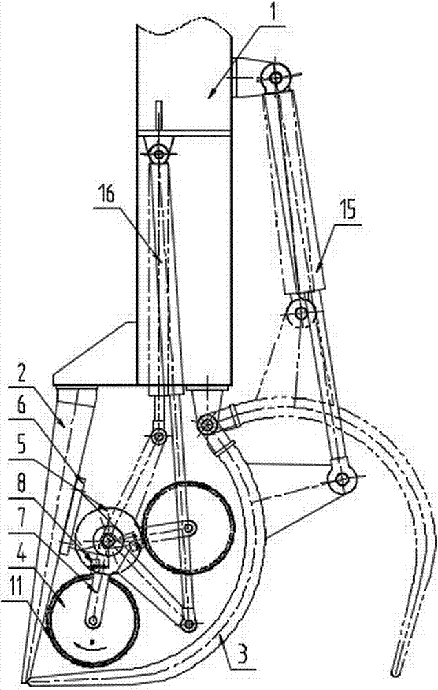
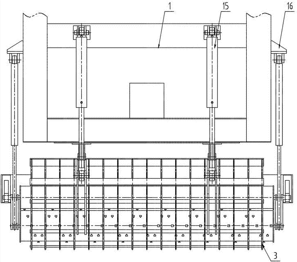
[0053] The utility model relates to a cleaning machine, which includes a grab bucket, and a crushing device for underwater crushing of dirt is arranged in the grab bucket. The crushing device includes a crushing drum 4 and an auxiliary drum 5. The crushing drum 4 can rotate at a high speed underwater, and the high-speed rotating crushing drum 4 and the auxiliary drum 5 cooperate to crush dirt.
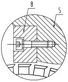
[0054] In this embodiment, the crushing device further includes a seat body 6, a V-shaped connecting rod 7 and a driving hydraulic cylinder 16, and the number of the seat body 6, the V-shaped connecting rod 7 and the driving hydraulic cylinder 16 is preferably two sets; Wherein, the cylinder ends of two sets of driving hydraulic cylinders 16 are all movably connected to the two ends of the grab bracket 1 through bearings, and the two sets of driving hydraulic cylinders 16 are symmetrical. Two sets of pedestals 6 are fixed in the grab bucket, and the shafts at two ends of the auxiliary ...
Embodiment 2
[0059] This embodiment is basically the same as Embodiment 1, the main difference is that: the outer surface of the auxiliary cylinder 5 is fixedly provided with a connecting strip 9, and the fixed knife 8 is fixed on the connecting strip 9 by bolts. Wherein, the connecting strip 9 is fixed or integrally formed on the auxiliary cylinder 5 by bolts.
Embodiment 3
[0061] The utility model relates to a cleaning machine, which includes a grab bucket, and a crushing device for underwater crushing of dirt is arranged in the grab bucket. The crushing device includes a crushing drum 4 and an auxiliary drum 5. The crushing drum 4 can rotate at a high speed underwater, and the high-speed rotating crushing drum 4 and the auxiliary drum 5 cooperate to crush dirt.
[0062] In this embodiment, the crushing device further includes a seat body 6, a V-shaped connecting rod 7 and a driving hydraulic cylinder 16, and the number of the seat body 6, the V-shaped connecting rod 7 and the driving hydraulic cylinder 16 is preferably two sets; Wherein, the cylinder ends of two sets of driving hydraulic cylinders 16 are all movably connected to the two ends of the grab bracket 1 through bearings, and the two sets of driving hydraulic cylinders 16 are symmetrical. Two sets of seat bodies 6 are fixed in the grab bucket, and the axles at the two ends of the auxil...
PUM
 Abstract
Description
Claims
Application Information
 - R&D
- Intellectual Property
- Life Sciences
- Materials
- Tech Scout
- Unparalleled Data Quality
- Higher Quality Content
- 60% Fewer Hallucinations
Browse by: Latest US Patents, China's latest patents, Technical Efficacy Thesaurus, Application Domain, Technology Topic, Popular Technical Reports.
© 2025 PatSnap. All rights reserved.Legal|Privacy policy|Modern Slavery Act Transparency Statement|Sitemap|About US| Contact US: help@patsnap.com


