High potential side energy supplying device of active electronic type photoelectric current mutual inductor

A current transformer and electronic technology, applied in the direction of inductors, voltage/current isolation, circuits, etc., can solve problems such as limited energy supply of lasers, difficult power supply methods, and untested lifespan, achieving compact structure and simple insulation packaging , use the effect of safety

Inactive Publication Date: 2009-01-14
安徽艺展电气设备有限公司
View PDF0 Cites 7 Cited by
  • Summary
  • Abstract
  • Description
  • Claims
  • Application Information

AI Technical Summary

Problems solved by technology

However, on the primary side of active transformers, the method of obtaining power is the biggest technical problem in the development
[0005] However, in the existing energy supply technology, when the bus current is small, the high-voltage side cannot obtain enough energy to supply the electronic circuits on the high-voltage side to work. In addition, the laser energy supply method is completely used. Because the laser supply energy is limited and it needs to work for a long time, other The life expectancy is yet to be tested, and it is in the experimental stage of product operation

Method used


Image

  • High potential side energy supplying device of active electronic type photoelectric current mutual inductor
  • High potential side energy supplying device of active electronic type photoelectric current mutual inductor
  • High potential side energy supplying device of active electronic type photoelectric current mutual inductor

Examples


Embodiment Construction

[0020] The active electronic photoelectric current transformer high-voltage side energy supply device proposed by the present invention is described in detail as follows in conjunction with the accompanying drawings:

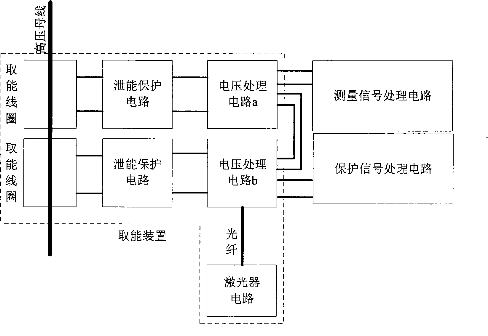
[0021] The overall structure of the energy supply device on the high voltage side of the active electronic photoelectric current transformer proposed by the present invention is as follows: figure 1 As shown; the device includes a circuit A composed of the first high-voltage energy-taking coil connected in sequence, the second energy leakage protection circuit, and the voltage processing circuit a, and the second high-voltage energy-taking coil connected in sequence, the second A circuit B composed of an energy leakage protection circuit, a voltage processing circuit b, and a laser component connected to the circuit B.

[0022] Working principle of the present invention:

[0023] Each energy harvesting coil collects the electrical energy on the bus through elec...


PUM


Abstract

The invention relates to an active electronic photoelectric current transformer high-voltage side power supply device, belonging to the field of power system technique; the device of the invention comprises a circuit A which consists of a first high-voltage energy storage coil, a first energy leakage protection circuit and a voltage processing circuit a which are sequentially connected one after another, a circuit B which consists of a second high-voltage energy storage coil, a second energy leakage protection circuit and a voltage processing circuit b which are sequentially connected one after another, and a laser component which is connected with the circuit B. The device of the invention has the advantages of small volume, compact structure, simple insulation encapsulation and safe usage, and can ensure the electronic transformer to work normally and continuously within an extremely great current range.

Description

technical field [0001] The invention belongs to the technical field of power systems, in particular to the structural design of high-voltage energy harvesting equipment. Background technique [0002] In recent years, with the development of digital technology, digital substation has become an inevitable trend, and the research of its main equipment, electronic transformer (also known as photoelectric transformer), has also made continuous progress. Electronic transformers are divided into active and passive. There are two types of source. Among them, the active type is developing rapidly, and there are already products running on the grid in China. The electronic transformer directly responds to the change of the measured analog quantity with its optical digital output. According to the standards of the International Electrotechnical Commission, the advantages of electronic current transformers are: the Rogowski coil is used as a primary converter to achieve large current ...

Claims


Application Information

Patent Timeline
Patent Type & Authority Applications(China)
IPC IPC(8): H01F38/32G01R15/18G01R15/24
Inventor 汪良明
Owner 安徽艺展电气设备有限公司
Why Eureka
Try Eureka