
Artificial foot

A technology of prosthetic feet and foot parts, applied in medical science, prosthetics, artificial legs, etc., can solve the problems of changing prosthetic feet, wandering, etc.

Active Publication Date: 2012-04-18
OTTO BOCK HEALTHCARE IP GMBH & CO KG
View PDF1 Cites 0 Cited by
  • Summary
  • Abstract
  • Description
  • Claims
  • Application Information

AI Technical Summary

Problems solved by technology

Disadvantageously, however, the load movement of the upper coupling element designed as a rocker changes the foot length of the prosthetic foot in the plantar region, so that undesired foot movement can occur, for example, under rocking loads.

Method used


Image

  • Artificial foot
  • Artificial foot
  • Artificial foot

Examples


Embodiment Construction

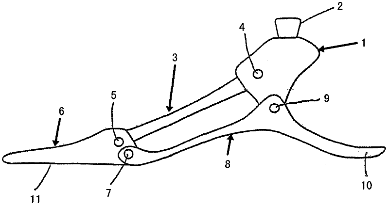
[0019] figure 1 The first embodiment of the foot according to the invention shown in FIG. 2 has a connecting part 1 which is provided on its upper side with an adapter nose 2 which is in the shape of a frustoconical upright on the head. The adapter nose 2 makes it possible to adjustably receive the tubular lower leg part of the lower leg prosthesis.

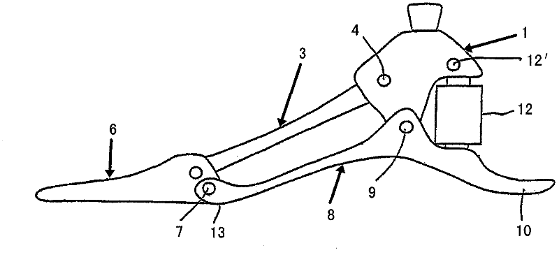
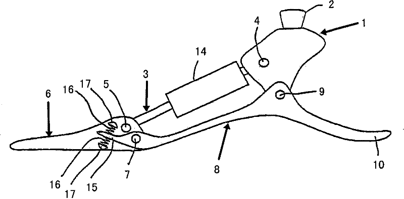
[0020] An upper coupling element 3 is connected to the connection part 1 via a swivel joint 4 . The other end of the upper coupling element is connected via a further swivel joint 5 to a forefoot part 6 by which the toe region of a natural foot is simulated. On the front foot part 6 , below the swivel joint 5 , there is a further swivel joint 7 , via which the lower coupling element 8 is connected to the front foot part 6 . The lower coupling element 8 is articulated on the lower end of the connecting part 1 via a swivel hinge 9 and has a nose which extends beyond the swivel hinge 9 into the free heel end 10 of the lower coupli...


PUM


Abstract

Disclosed is an artificial foot comprising a connecting part (1) for a lower leg part, a forefoot part (6) which is hingedly connected to the connecting part (1) by means of an upper coupling element (3) and a lower coupling element (8) in such a way that an angular position of the connecting part (1) controls an angular position of the forefoot part (6), one of the coupling elements (3, 8) extending to a heel area of the foot. In order to prevent the effective foot length from changing when putting weight on the foot, the lower coupling element (8) extends to the heel area.

Description

technical field [0001] The invention relates to a prosthetic foot with a connection part for the lower leg part and with a forefoot part to which the connection part is articulated by means of an upper coupling element and a lower coupling element, so that the angular position of the connection part controls the forefoot part , wherein one of the coupling elements extends all the way into the heel region of the foot. Background technique [0002] Such a prosthetic foot is described in the non-previously published German patent application DE 10 2004 031 562 A1, the disclosure content of which is cited. Since the forefoot part is coupled to the connecting part for the lower leg part via two coupling elements, a positive coupling of the connecting part and the forefoot part with regard to the angular position takes place for the first time. Changing the angular position of the link or calf section with the hips results in a proportional lift of the forefoot. The prosthetic f...

Claims


Application Information

Patent Timeline
Patent Type & Authority Patents(China)
IPC IPC(8): A61F2/66
CPCA61F2002/5006A61F2002/6635A61F2002/5075A61F2/66A61F2002/6685A61F2002/6621A61F2002/6678A61F2002/6642
Inventor L·莫斯勒
Owner OTTO BOCK HEALTHCARE IP GMBH & CO KG
Learn More