
Image forming apparatus and image forming method

An image and image data technology, applied in the field of image forming device and image forming, can solve problems such as mismatch between correction and error distribution, decrease in image quality, uneven density, etc., and achieve the effect of reducing image quality degradation and eliminating contour features

Inactive Publication Date: 2009-02-04
CANON KK
View PDF3 Cites 7 Cited by
  • Summary
  • Abstract
  • Description
  • Claims
  • Application Information

AI Technical Summary

Problems solved by technology

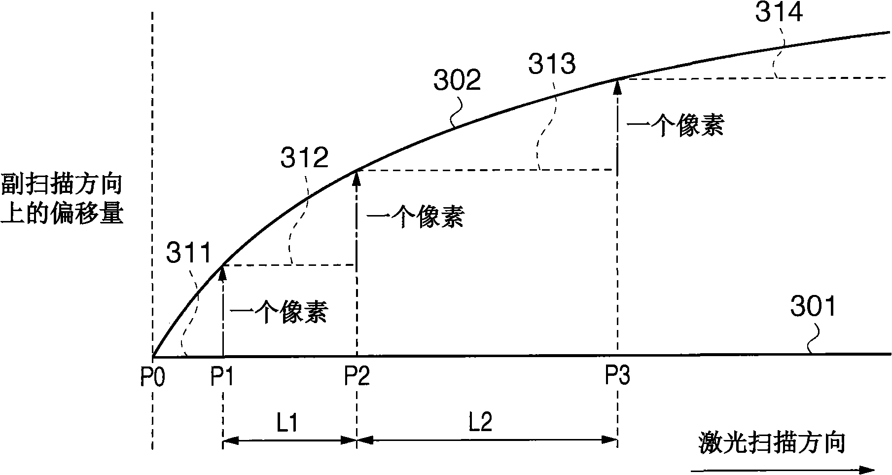
However, this scan line switching process is completed in units of one pixel, so an offset of less than one pixel remains in the sub-scanning direction
However, depending on the image forming method of the image data for performing registration error correction, if the correction of more than one pixel and the correction of less than one pixel are directly performed on the image data, the image deteriorates
Therefore, a correction of more than one pixel at a scan line changing point does not match the error distribution, and the mismatch manifests itself as density unevenness or texture, degrading image quality

Method used


Image

  • Image forming apparatus and image forming method
  • Image forming apparatus and image forming method
  • Image forming apparatus and image forming method

Examples


no. 1 example

[0038] A first embodiment of the present invention will be described with reference to the drawings. In the first embodiment, the deviation of the actual scanning line from the ideal scanning line (i.e., the scanning line parallel to the rotation axis of the photosensitive drum) that should have been formed by scanning the surface of the photosensitive drum with the laser beam is obtained by converting the dot image data to Move the same amount in the opposite direction to eliminate. Image deterioration such as unevenness due to registration error correction is prevented. In addition, image degradation caused by dithering processing on point image data after registration error correction is also prevented.

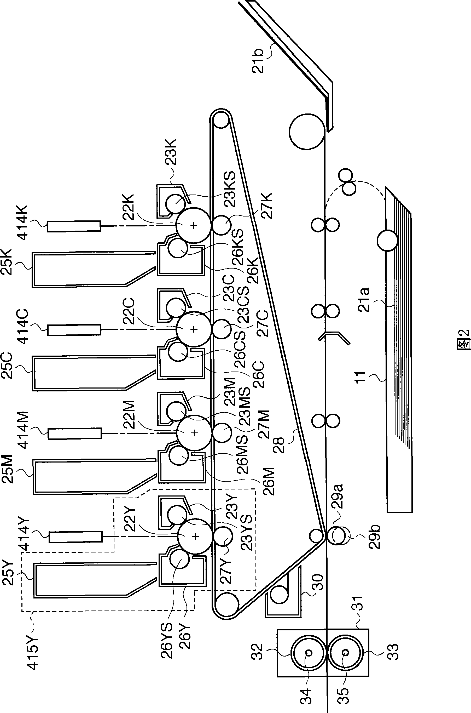
[0039] A structural example of a laser beam printer as an example of an image forming apparatus applicable to an embodiment of the present invention and an image correction method performed by the laser beam printer will be described below. This embodiment is applicable ...


PUM


Abstract

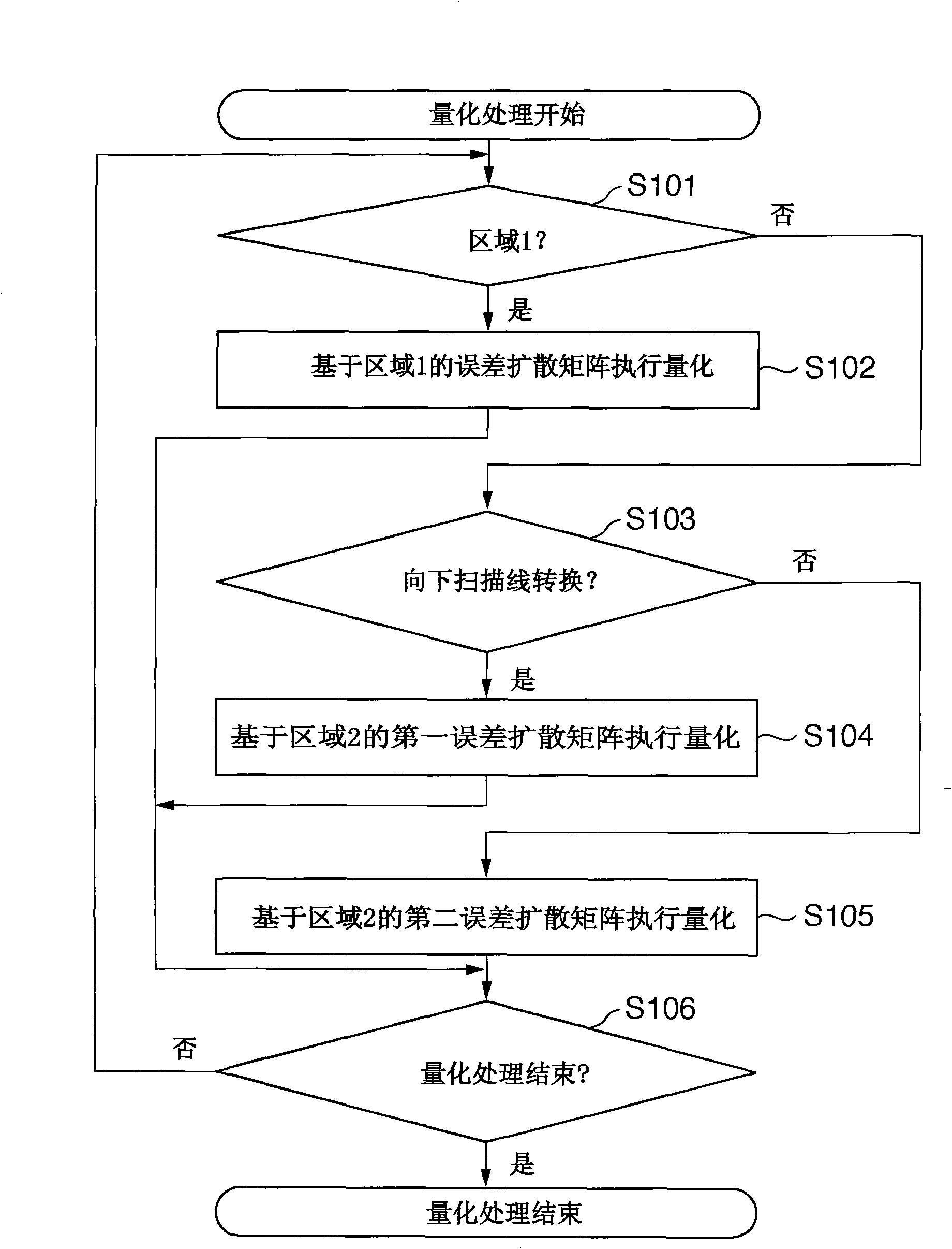
The invention provides an image forming device and an image forming method. It is determined whether the pixel of interest in image data to be processed belongs to area 1 not close to a scan line changing point where a scan line changing process is done (S101). If the pixel of interest belongs to area 1, an error diffusion process is performed using an error diffusion matrix for area 1 (S102). If the pixel of interest belongs to area 2 close to the scan line changing point, the error diffusion process is performing using an error diffusion matrix for downward scan line changing for area 2 when the scan line changing process is changing to a lower line, or an error diffusion matrix for upward scan line changing for area 2 when the scan line changing process is changing to an upper line.

Description

technical field [0001] The present invention relates to an image forming apparatus and an image forming method, and more particularly, to a color image forming apparatus and a color image forming method that independently form an image for each color component, such as a laser beam printer (LBP ), digital copiers, or multifunction printers (MFPs) that utilize electronic camera processing. Background technique [0002] As a color image forming apparatus such as a printer or a copying machine, there is known a tandem type color image forming apparatus which includes electrophotographic image forming units in a number equal to the number of color components, and is sequentially processed by the image forming units. The toner images of the respective color components are transferred onto the printing medium. The image forming unit for each color includes a developing unit and a photosensitive drum. The tandem-type color image forming apparatus is known to have a plurality of f...

Claims


Application Information

Patent Timeline
IPC IPC(8): G03G15/01G03G15/00H04N1/52H04N1/00
CPCH04N1/0473G03G15/0178H04N2201/04787G03G15/0194G03G2215/0129H04N1/1135G03G2215/0161H04N2201/04793
Inventor 仲村康幸
Owner CANON KK
Learn More