Driver and driver circuit for pixel circuit

A driver circuit, pixel circuit technology, applied in the direction of instruments, static indicators, etc., can solve the problem of long stabilization time of current programming

Inactive Publication Date: 2009-02-11
HIMAX TECH LTD
View PDF3 Cites 18 Cited by
  • Summary
  • Abstract
  • Description
  • Claims
  • Application Information

AI Technical Summary

Problems solved by technology

However, when faced with low gray levels, current programming suffers from longer settling time
This situation is exacerbated as the panel size increases

Method used


Image

  • Driver and driver circuit for pixel circuit
  • Driver and driver circuit for pixel circuit
  • Driver and driver circuit for pixel circuit

Examples


Embodiment Construction

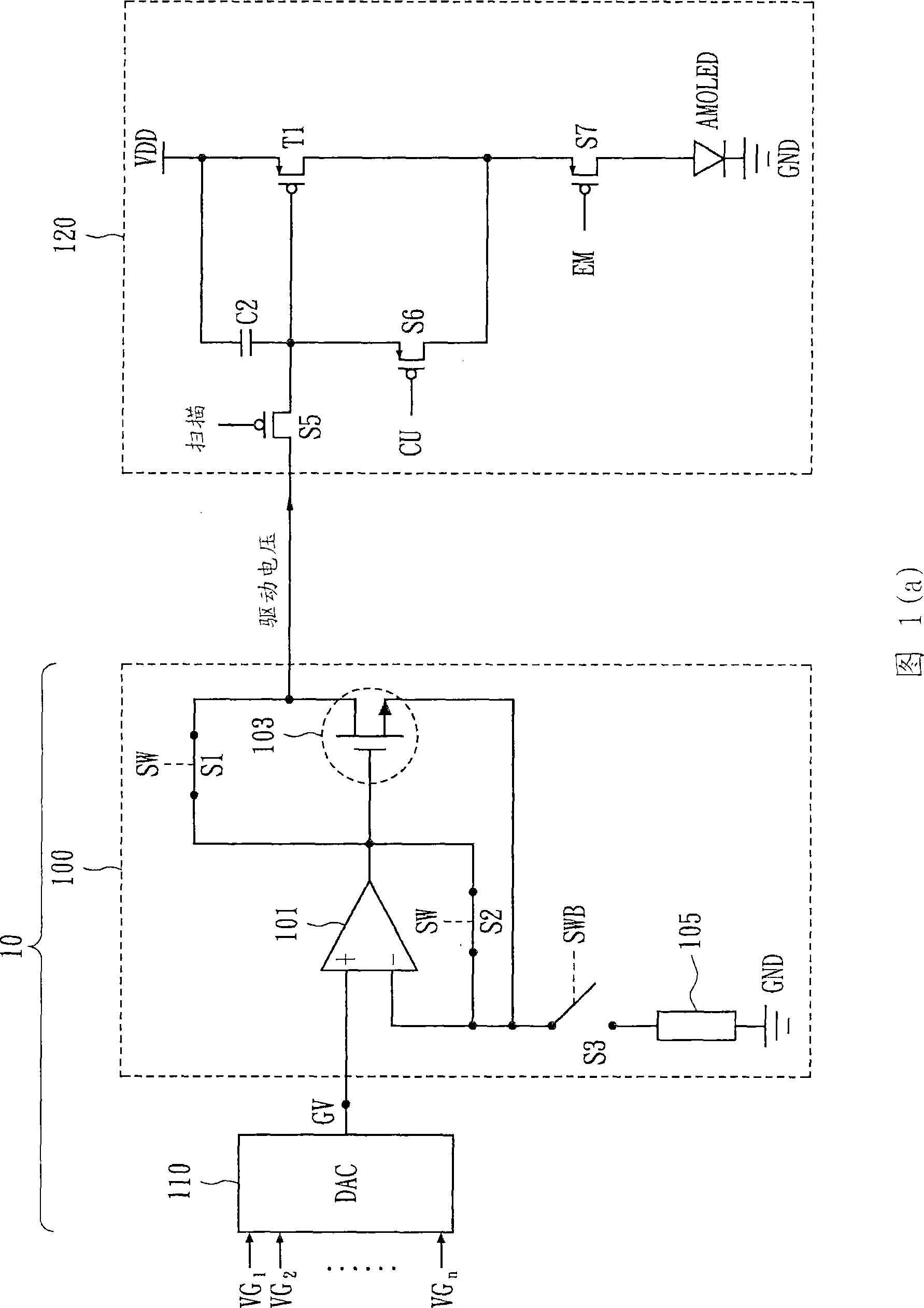
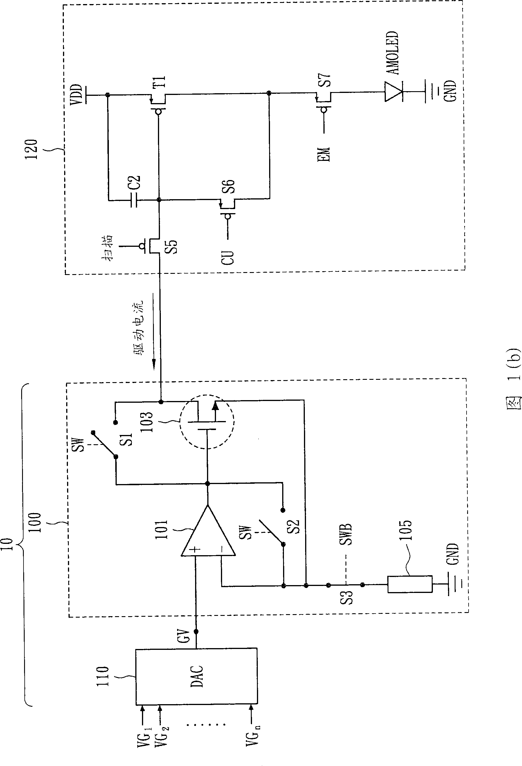
[0031] 1(a) and 1(b) show a driver 10 applied to a pixel circuit 120 according to an embodiment of the present invention. The pixel circuit 120 includes a capacitor, which is charged according to the programming of the present invention. The driver 10 includes a digital-to-analog converter 110 and an output stage 100 . The digital-to-analog converter 110 receives a pixel value, and selects a gamma voltage VG corresponding to the pixel value from a plurality of gamma voltages VG1???-VGn to output. The output stage 100 is equivalent to a unity gain buffer, which includes an operational amplifier 101 , a first switch S1 , a second switch S2 , a third switch S3 , a fourth switch 103 and a resistor element or an impedance 105 . The operational amplifier 101 receives the gamma voltage VG from the digital-to-analog converter 110 . The first switch S1 and the second switch S2 are set to determine a feedback path coupled to the output terminal and the negative input terminal of the o...


PUM


Abstract

The invention provides a driver used for pixel circuit and a driver circuit. The driver has a digital-to-analog converter receiving a pixel value and outputting a gamma voltage corresponding to the pixel value and an output stage which provides a driving voltage and a driving current corresponding to the gamma voltage output from the converter, where the driving voltage and current are provided during the first and second stages of a programming period, respectively.

Description

technical field [0001] The present invention relates to a driver and a driver circuit applied to a pixel circuit, and more particularly to a driver and a driver circuit using a hybrid driving technique. Background technique [0002] In the field of Active Organic Light Emitting Diodes (AMOLED), AMOLED displays are still limited to small area applications due to the shortcomings of the programming methods in the market. Generally, the programming of the AMOLED panel is divided into two methods: voltage programming and current programming. The advantages of voltage programming include shorter settling time and simple gamma correction. However, voltage programming exhibits poor compensation for threshold voltage and carrier mobility shifts due to process variation. Current programming can overcome the shortcomings of voltage programming, that is, it can provide perfect compensation for threshold voltage and carrier mobility drift. However, when faced with low gray levels, th...

Claims


Application Information

Patent Timeline
Patent Type & Authority Applications(China)
IPC IPC(8): G09G3/32
CPCG09G3/2077G09G2300/0861G09G2300/0842G09G2310/0251G09G3/325G09G2310/027G09G3/3233G09G3/3291G09G2320/0276G09G3/3283
Inventor 王振宇
Owner HIMAX TECH LTD
Why Eureka
Try Eureka