Method and apparatus for intra-frame prediction

An intra-frame prediction and prediction block technology, applied in the field of image decoding, can solve the problems of unattainable decoding speed, affecting decoding speed, complexity, etc., and achieve the effect of saving prediction time and improving decoding speed.

Inactive Publication Date: 2009-02-11
SHENZHEN COSHIP ELECTRONICS CO LTD
View PDF0 Cites 27 Cited by
  • Summary
  • Abstract
  • Description
  • Claims
  • Application Information

AI Technical Summary

Problems solved by technology

[0046] In the existing intra prediction method, it is necessary to obtain the absolute coordinates in the image of the lower boundary pixels adjacent to the upper prediction block adjacent to the current prediction block and the right boundary pixels adjacent to the left prediction block through complex calculations, and query in the cache according to the absolute coordinates Calculate the lower boundary pixel value adjacent to the upper prediction block and the right boundary pixel value adjacent to the left prediction block. This calculation method is very time-consuming
Especially for intra-frame prediction with a 4×4 matrix, the process of calculating the right boundary pixel value of the adjacent left prediction block and the lower boundary pixel value of the adjacent upper prediction block of each 4×4 sub-block is more complicated, which greatly affects the decoding. speed
Moreover, the H.264 video compression standard is very complicated, and the computer needs a lot of calculations to decode the image. If the calculation speed of the computer is not enough or the calculation method is too complicated, the decoding speed cannot meet the requirements of people watching videos

Method used


Image

  • Method and apparatus for intra-frame prediction
  • Method and apparatus for intra-frame prediction
  • Method and apparatus for intra-frame prediction

Examples


Embodiment Construction

[0064] In order to make the object, technical solution and advantages of the present invention clearer, the present invention will be further described in detail below in conjunction with the embodiments and accompanying drawings.

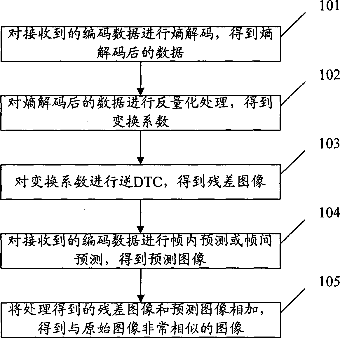
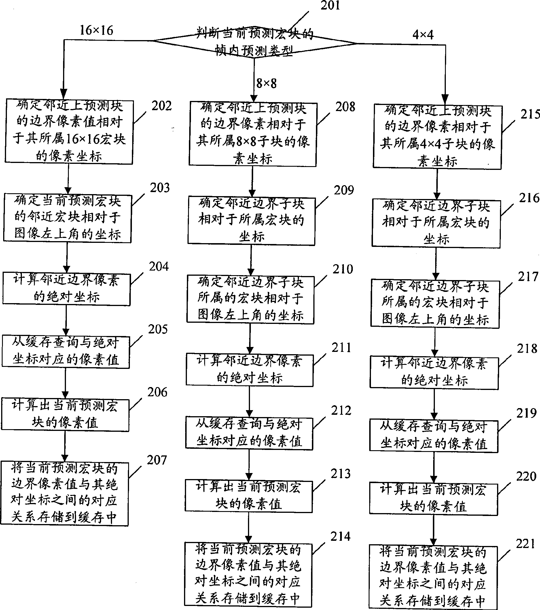
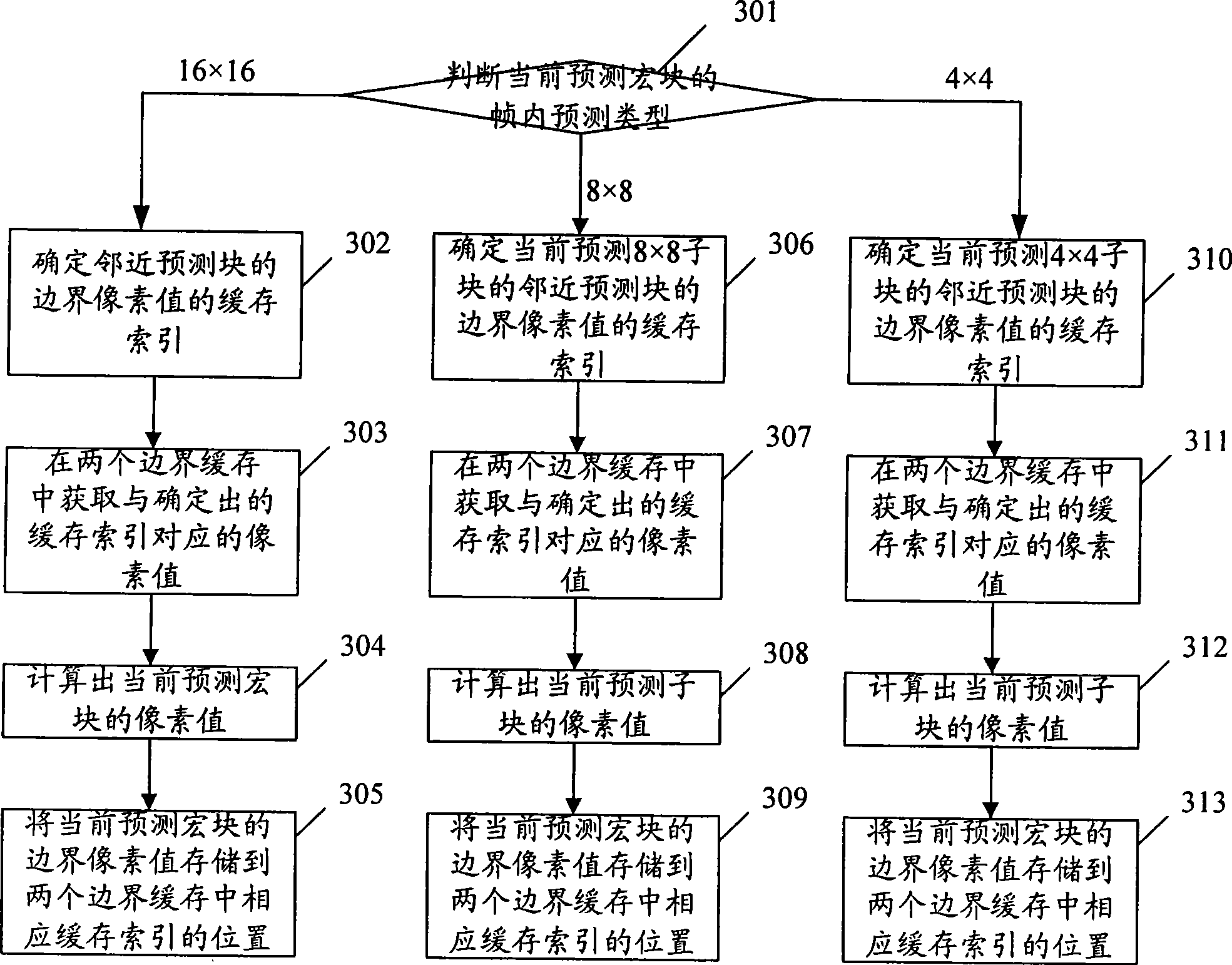
[0065] In the process of intra prediction, it is necessary to obtain the lower boundary pixel value of the adjacent upper prediction block and the right boundary pixel value of the adjacent left prediction block of the current prediction block, and according to the acquired lower boundary pixel value of the adjacent upper prediction block and the adjacent left prediction The pixel value of the current prediction block is calculated from the right boundary pixel value of the block. In the present invention, the lower boundary pixel value of the adjacent upper prediction block of the current prediction block is stored in the lower boundary buffer, and the right boundary pixel value of the adjacent left prediction block of the current prediction block ...


PUM


Abstract

The invention discloses a method and a device for intra-frame prediction. The method for the intra-frame prediction comprises the steps of (1) determining the row caching index of a lower boundary pixel value which is near to an upper prediction block of a current prediction block, and determining line caching index of a right boundary pixel value which is near to a left prediction block of the current prediction block; (2) taking a corresponding pixel value of the row caching index of the lower boundary pixel value which is near to the upper prediction block obtained in the lower boundary cache as the lower boundary pixel value which is near to the upper prediction block of the current prediction block; regarding the corresponding pixel value of the line caching index of the left boundary pixel value obtained in the right boundary cache as the right boundary pixel value which is near to the left prediction block of the current prediction block; (3) calculating the pixel value of the current prediction block according to the obtained lower boundary pixel value which is near to the upper prediction block and the right boundary pixel value which is near to the left prediction block. The scheme greatly saves prediction time and improves decoding speed of images.

Description

technical field [0001] The present invention relates to image decoding technology, in particular to a method and device for intra-frame prediction in image decoding. Background technique [0002] see figure 1 , for the image decoding process in the H.264 standard, including the following steps: [0003] Step 101, perform entropy decoding on the received coded data to obtain entropy decoded data. [0004] Step 102, performing inverse quantization processing on the entropy-decoded data to obtain transform coefficients. [0005] Step 103, performing an inverse discrete cosine transform (DTC, Discrete Cosine Transform) on the transform coefficients to obtain a residual image. [0006] Each pixel value of the residual image is the difference between the pixel value of the corresponding point in the original image minus the pixel value of the corresponding point in the predicted image. The so-called predicted image is an image close to the original image. [0007] Each image i...

Claims


Application Information

Patent Timeline
Patent Type & Authority Applications(China)
IPC IPC(8): H04N7/26H04N7/50H04N19/176H04N19/44H04N19/593
Inventor 豆成权
Owner SHENZHEN COSHIP ELECTRONICS CO LTD
Why Eureka
Try Eureka