
Optimizing method for wireless sensor network node laying oriented to area monitoring

A wireless sensor and area monitoring technology, applied in data exchange networks, transmission systems, digital transmission systems, etc., can solve problems such as poor operability, low algorithm search efficiency, and inability to guarantee

Inactive Publication Date: 2011-06-01
SHANGHAI INST OF MICROSYSTEM & INFORMATION TECH CHINESE ACAD OF SCI
View PDF0 Cites 0 Cited by
  • Summary
  • Abstract
  • Description
  • Claims
  • Application Information

AI Technical Summary

Problems solved by technology

The disadvantage of the VFA algorithm is that it cannot guarantee that the entire layout adjustment process is carried out in the direction of optimization, nor can it be guaranteed to have convergence, and the actual operability is very poor.
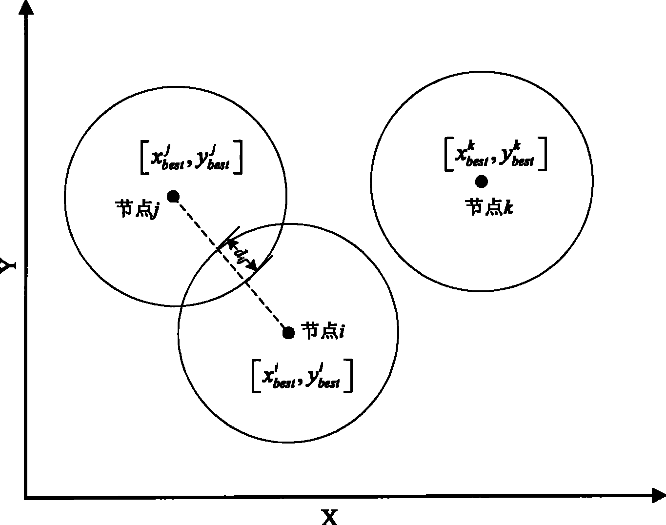
Some global optimization algorithms, such as genetic algorithm and particle swarm optimization algorithm, are also used to solve this problem [Xiaoling Wu, Lei Shu, Jie Yang, et al, "Swarm based sensor deployment optimization in ad hocsensor networks," ICESS 2005, LNCS 3820, PP.533-541, 2005], the coverage of the monitoring area is modeled as an objective function to be optimized, hoping to find a set of optimal node location sets so that the monitoring area can reach the best coverage, but facing a large number of sensor nodes For high-dimensional optimization problems, these algorithms generally have problems such as low search efficiency, easy to fall into local extremum, and even cannot be used at all

Method used


Image

  • Optimizing method for wireless sensor network node laying oriented to area monitoring
  • Optimizing method for wireless sensor network node laying oriented to area monitoring
  • Optimizing method for wireless sensor network node laying oriented to area monitoring

Examples


Embodiment Construction

[0065] In order to make the objectives, technical solutions and advantages of the present invention clearer, the following describes the embodiments of the present invention in detail with reference to the accompanying drawings.

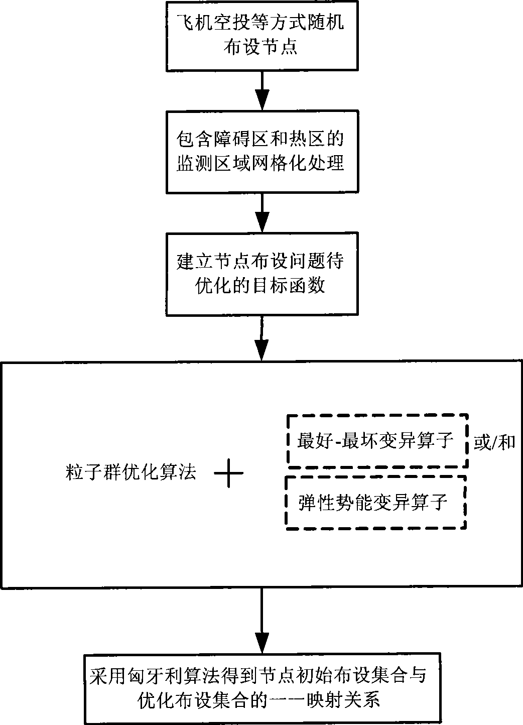
[0066] Assuming that the monitoring area is a rectangular area of ​​50m×50m, the monitoring area includes a 10m×10m hot zone and a 10m×10m obstacle zone. The detection range of each sensor is a disc with itself as the center and a radius of r=5m. This embodiment is applied to the deployment stage of wireless sensor network nodes for area monitoring applications, such as figure 1 As shown, it specifically includes the following steps:

[0067] 1) Determine the number N of sensors to be deployed. In this embodiment, ε = 0.25, by

[0068] N = A A s ( 1 + ϵ )

[0069] Get N≈40. Randomly disperse 40 sensors into the monitoring area by airdrop, etc., to obtain the initial position set P of the sensors init .

[0070] 2) Use the gr...


PUM


Abstract

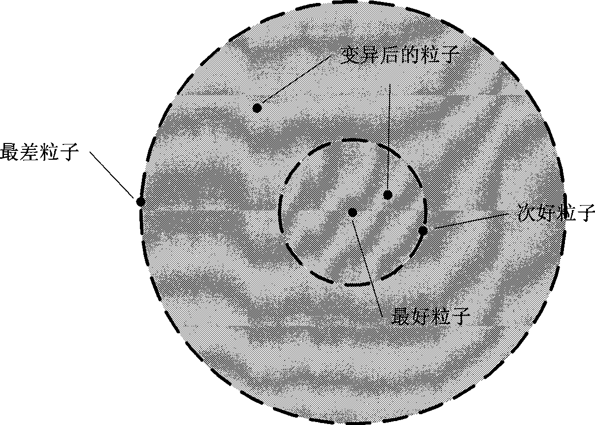
The invention discloses an optimization method for deploying the nodes of a wireless sensor network for regional monitoring. The method comprises the following steps: firstly, reticulating the wireless sensor network monitoring range which contains obstruction regions and hotspots, then creating an objective function which is to be optimized according to a node-detecting model and requirements for covering various types of regions, solving the optimal node-deployment position set by the particle-group optimizing algorithm, and designing two variation operators of the best-the worst variation and an elastic potential-energy in combination with the character of deployment so as to quicken the convergence-velocity of the particle-group optimizing algorithm, and finally using the Hungarian algorithm to obtain the optimal one-to-one mapping relationship between the original node-deploying position set and the optimized node-deploying position set so as to ensure that the nodes consume the least total energy for moving to the optimized deployment position. By the invention, the problem of higher-dimension optimization before node deployment optimization of wireless sensor network can beeffectively solved, and the coverage rate of the regions under monitoring can be improved from the angle of object detection function.

Description

Technical field [0001] The invention relates to an optimization method for wireless sensor network node deployment oriented to area monitoring, and is particularly suitable for target detection applications in wireless sensor networks. Background technique [0002] With the rapid development and maturity of sensor technology, wireless communication technology, embedded computing technology, and distributed information processing technology, micro sensor networks with perception, computing and communication capabilities have begun to appear on a large scale. Its purpose is to cooperatively perceive, collect and process the information of sensing objects in the network coverage area and send it to observers. It is mainly used in military scenes, target tracking, environment detection, and space exploration. For many applications of wireless sensor networks, due to the large number of sensor nodes or the unreachability of the area that needs to be monitored, the nodes are often depl...

Claims


Application Information

Patent Timeline
Patent Type & Authority Patents(China)
IPC IPC(8): H04L12/26H04L12/28H04L29/08
Inventor 余志军魏建明刘海涛潘强
Owner SHANGHAI INST OF MICROSYSTEM & INFORMATION TECH CHINESE ACAD OF SCI
Learn More