Degaussing for write head

A technology of writing magnetic head and degaussing, which is applied in the direction of magnetic head demagnetization device, instrument, calculation, etc., and can solve data erasure and other problems

Inactive Publication Date: 2009-03-18
TEXAS INSTR INC
View PDF0 Cites 0 Cited by
  • Summary
  • Abstract
  • Description
  • Claims
  • Application Information

AI Technical Summary

Problems solved by technology

Generally, during reading, the write head current Iw is turned off, but some heads (electrodes) maintain a small amount of magnetization, which may undesirably cause some data to be erased

Method used


Image

  • Degaussing for write head
  • Degaussing for write head
  • Degaussing for write head

Examples


Embodiment Construction

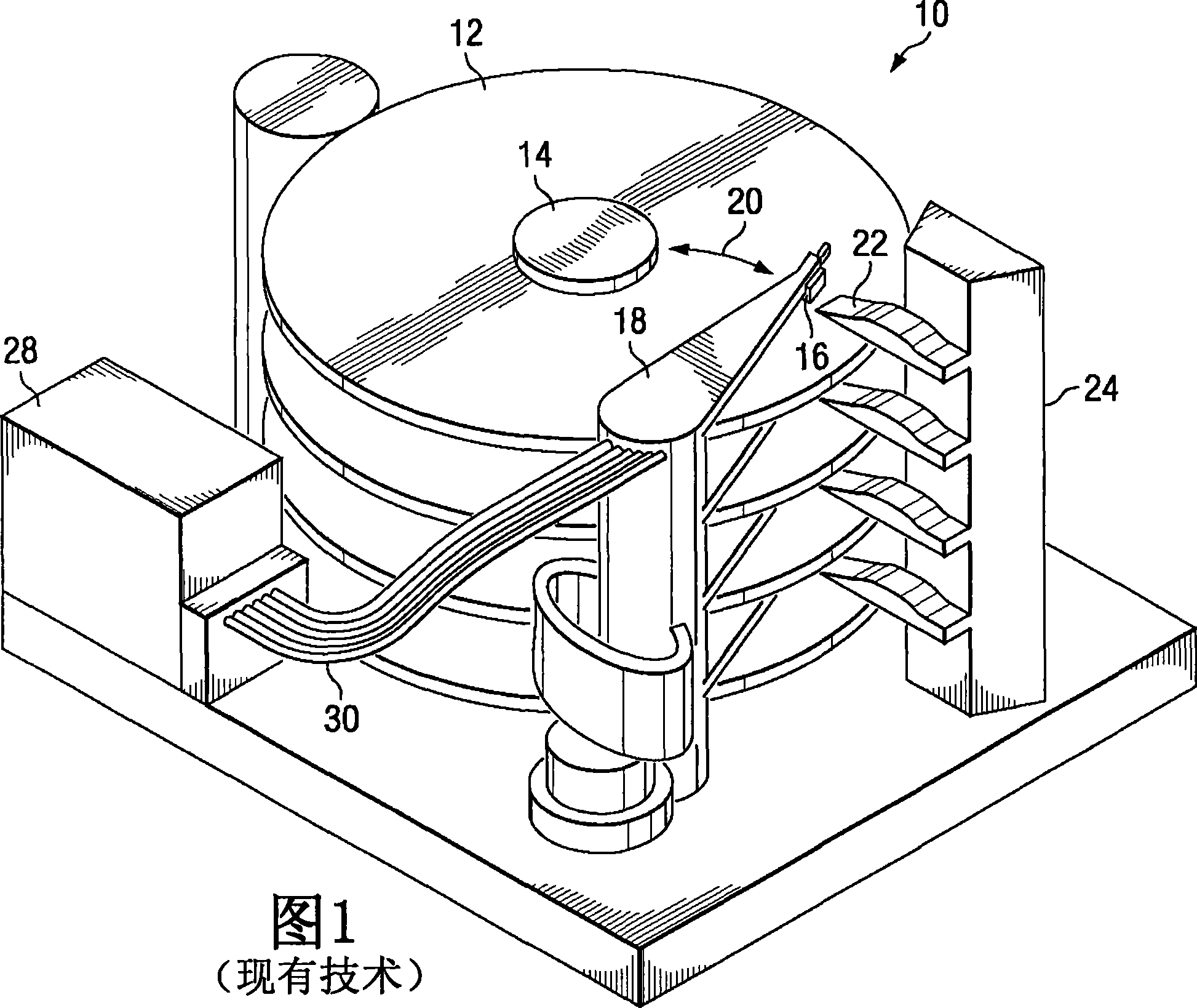
[0015] [008] FIG. 1 depicts a conventional hard disk drive 10 having a plurality of disks and associated actuators that can be positioned on the disks between an operative position and a retracted parked position. It can be seen that each disk 12 is mounted on a shaft 14 and has associated therewith a head 16 carried by a suspension 18 . It can be seen that each head 16 is placed on the disk surface as shown at 20 by a respective arm 18 and is also retractable via ramp 22 to a parked position away from head 22 and above lower portion 24 . Actuator control circuitry 26 housed in housing 28 is coupled to and controls each arm 18 by cables 30 .

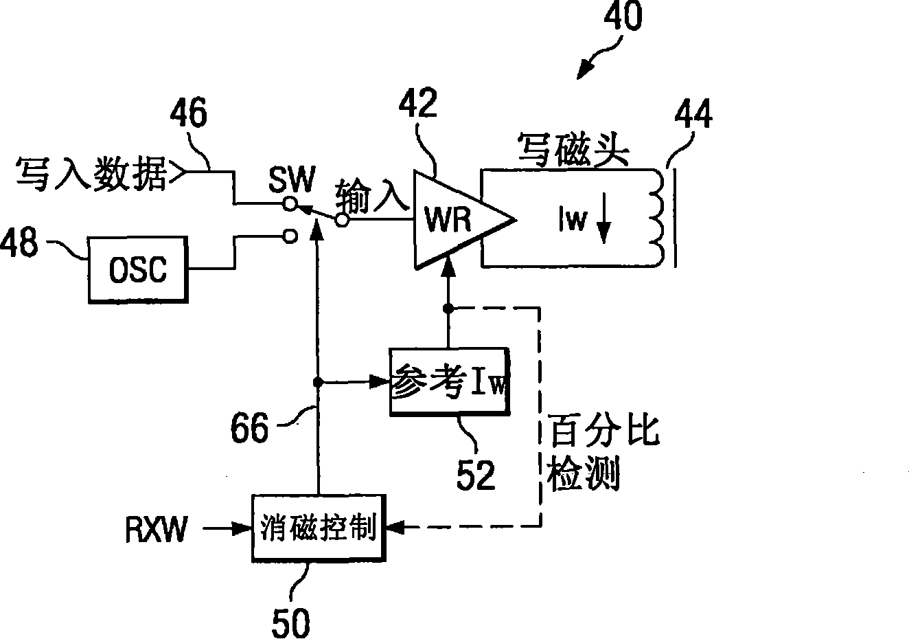
[0016] 【009】Refer now figure 2 , which shows a block diagram of the write circuit designated 40 . It can be seen that the write circuit 40 comprises a write head driver 42 (WR) driving a voice coil 44, and has an input selectively coupled by a switch Sw to a write data input line 46 or an oscillator 48 (OSC). When the driver input is ...


PUM


Abstract

A write head degaussing circuit (40) and methodology configured to end the degaussing signal (66) a selectable percentage short of the tapered degaussing waveform, starting the degaussing of the write head current Iw at a percentage less than Iw, removing any overshoot of the degaussing signal, and any combination of the above.

Description

technical field [0001] [001] The present invention relates generally to hard disk drives and, in particular, to degaussing write heads. Background technique [0002] [002] A hard disk drive generally includes one or more rotating disks stacked on top of each other on a shaft, a disk drive controller, a rotary actuator, and actuator retraction circuitry. These components are typically located on a chassis or in an enclosure and are powered from an external cable connector. [0003] [003] A rotary actuator comprises an arm equipped with a magnetic head for reading and writing data in generally radially concentric tracks in the recording layer of a single magnetic disk. The actuator is typically driven by a voice coil motor (VCM). Cables are connected to the actuators to carry signals to and from the heads and to power the VCM. A disk drive controller is generally an electronic circuit that controls all functions of a hard disk drive. [0004] [004] During the writing proce...

Claims


Application Information

Patent Timeline
Patent Type & Authority Applications(China)
IPC IPC(8): G06F12/00
CPCG11B5/465G11B2005/0018
Inventor M·桥爪T·广泽
Owner TEXAS INSTR INC
Why Eureka
Try Eureka