Continuous flow micro-pump

A micropump and pump body technology, applied in the field of continuous flow micropumps, can solve the problems of difficult continuous and stable fluid transmission, difficult gas transmission, small flow rate, etc., and achieve the effect of small volume, large pump flow rate and low cost

Inactive Publication Date: 2010-06-02
NAT UNIV OF DEFENSE TECH
View PDF3 Cites 2 Cited by
  • Summary
  • Abstract
  • Description
  • Claims
  • Application Information

AI Technical Summary

Problems solved by technology

[0005] 1. Since the reciprocating micropump uses the vibration of mechanical parts to drive the fluid, it is difficult to achieve continuous and stable transmission of the fluid. This is the biggest working defect of the reciprocating micropump
[0006] 2. The continuous flow micropump is mainly based on the direct conversion of non-mechanical energy into fluid continuous flow. The flow rate is small, and its working performance is greatly affected by the fluid performance. It is only suitable for a small part of the fluid, and it is difficult to realize the transmission of gas.

Method used


Image

  • Continuous flow micro-pump
  • Continuous flow micro-pump
  • Continuous flow micro-pump

Examples


Embodiment Construction

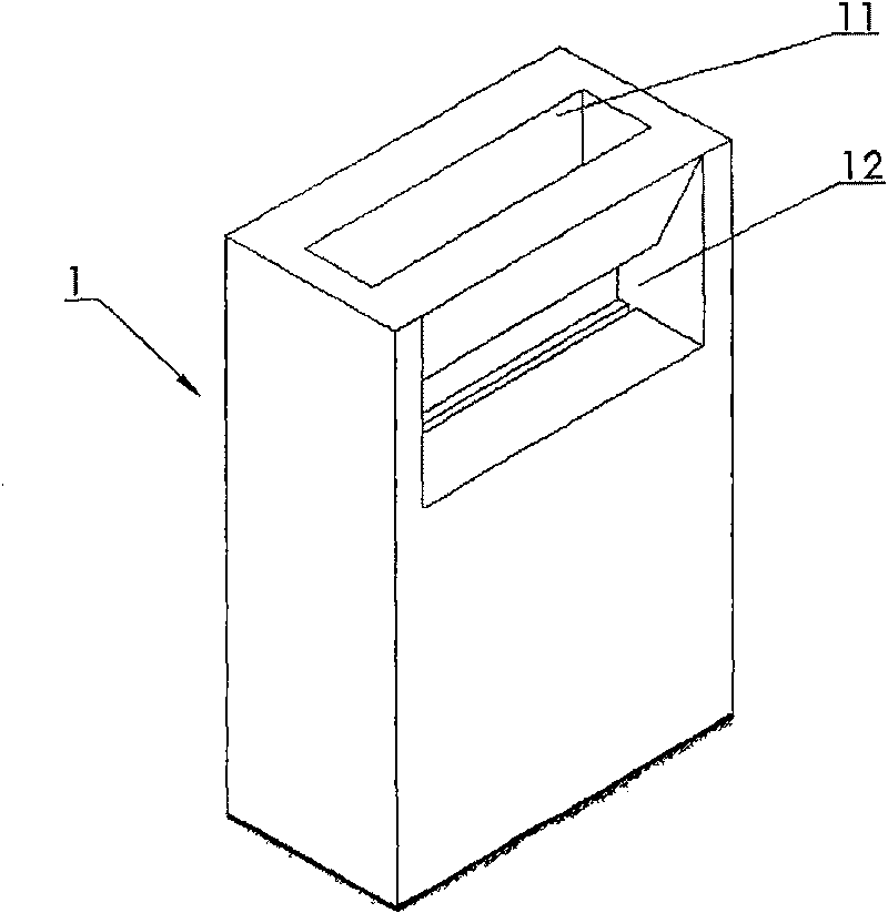
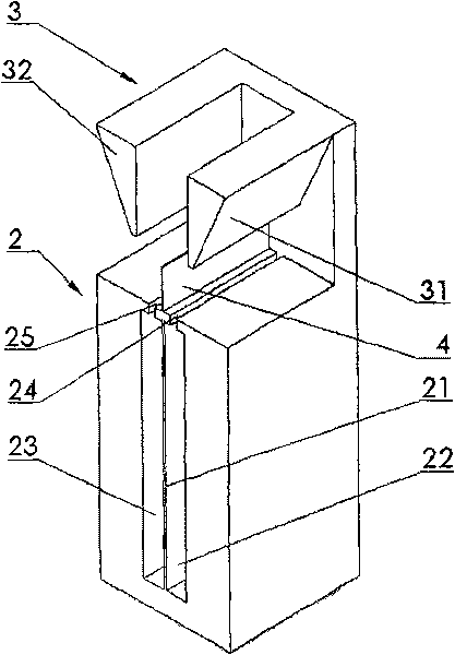
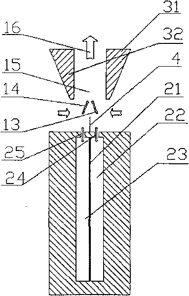
[0037] See attached Figure 1~2 , the pump body 1 of this embodiment of a continuous flow micropump of the present invention, its external dimensions are 20 × 50 × 70mm 3 , the shell is made of non-flexible hard aluminum alloy material; the vibration film 21 is made of rubber film material with good elasticity and flexibility, which is rectangular and driven by piezoelectric vibration; the guide baffle 4 is made of aluminum alloy sheet profile, with a size of 0.2 ×40×6mm 3 ; The cavity depth of the first cavity 22 and the second cavity 23 match the length of the vibrating membrane 21, both of which are 5mm; the first outlet 24 and the second outlet 25 are in the same shape as a narrow slit, and the cross-sectional size of the outlet is 40mm 2 ; And the outlet 11 can generally be made into a nozzle with a horn-shaped section, and the cross-sectional size of the outlet of the outlet 11 in the present embodiment is 10 * 40mm 2 , the entrance 12 is a frustum-shaped channel that ...


PUM


Abstract

The invention relates to a continuous-flow micro pump which is provided with a pump body (1); the upper part of pump body (1) is provided with a first flow splitting baffle (31) and a second flow splitting baffle (32), and an outlet (11) is formed between the two baffles; the lower part of the pump body (1) is provided with a dual-jet flow stimulating mechanism (2) which forms an opening (12) withthe two baffles; a vibrating diaphragm of the continuous-flow micro pump separates a cavity of the pump body (1) into a first cavity body (22) and a second cavity body (23); a flow guiding baffle (4)is arranged between the upper part and the lower part of the pump body (1); the continuous-flow micro pump sucks the fluid at two sides of the pump body through an inlet (12) by the dual-jet flow stimulating mechanism (2) and discharges the fluid through the outlet (11). The continuous-flow micro pump solves the problems that the continuous and stable transfer of the reciprocating-type micro pumpfluid is difficult and the flow of the continuous micro pump is small, has the advantages of simple structure, low cost and easy integration with other micro-controlled elements and is suitable for batch production.

Description

technical field [0001] The invention relates to a pump for fluid transmission, in particular to a continuous flow micropump driven by a synthetic double-jet excitation mechanism. Background technique [0002] Since Professors Smits and Wallmark of Stanford University in the United States first successfully developed a piezoelectric-driven peristaltic micromechanical pump in 1980, micropumps have been a hot spot in MEMS (microelectromechanical systems) research. At present, micropumps have been successfully applied in the fields of aerospace vehicles, robots, automobiles, medical equipment, biological genetic engineering, and micro-machines. The wide application and great research value of the micropump make it occupy an important position in the current microactuator research, and its development level has been considered an important symbol of the development of MEMS technology. [0003] Micropumps can be divided into two categories according to their pump flow characteris...

Claims


Application Information

Patent Timeline
Patent Type & Authority Patents(China)
IPC IPC(8): F04B45/04F04B43/02F04F5/00F04B53/00
Inventor 罗振兵夏智勋王林王德全胡建新
Owner NAT UNIV OF DEFENSE TECH
Why Eureka
Try Eureka