

Synthetic jetting excitor with single-membrane, double openings and double cavities
A technology for synthesizing jets and exciters, applied in the directions of fluid flow, mechanical equipment, etc., can solve problems such as ballast of the vibrating membrane of the exciter, and achieve the effect of wide synthetic jet, simple structure and small volume
- Summary
- Abstract
- Description
- Claims
- Application Information
AI Technical Summary
Problems solved by technology
Method used
Image

Examples
Embodiment 1
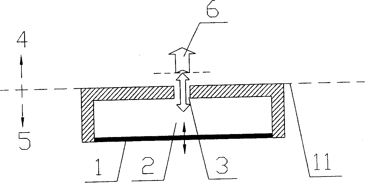
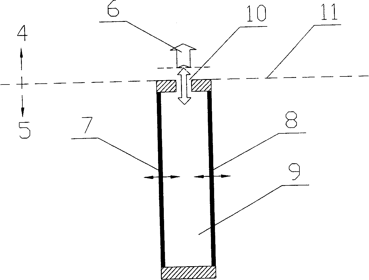
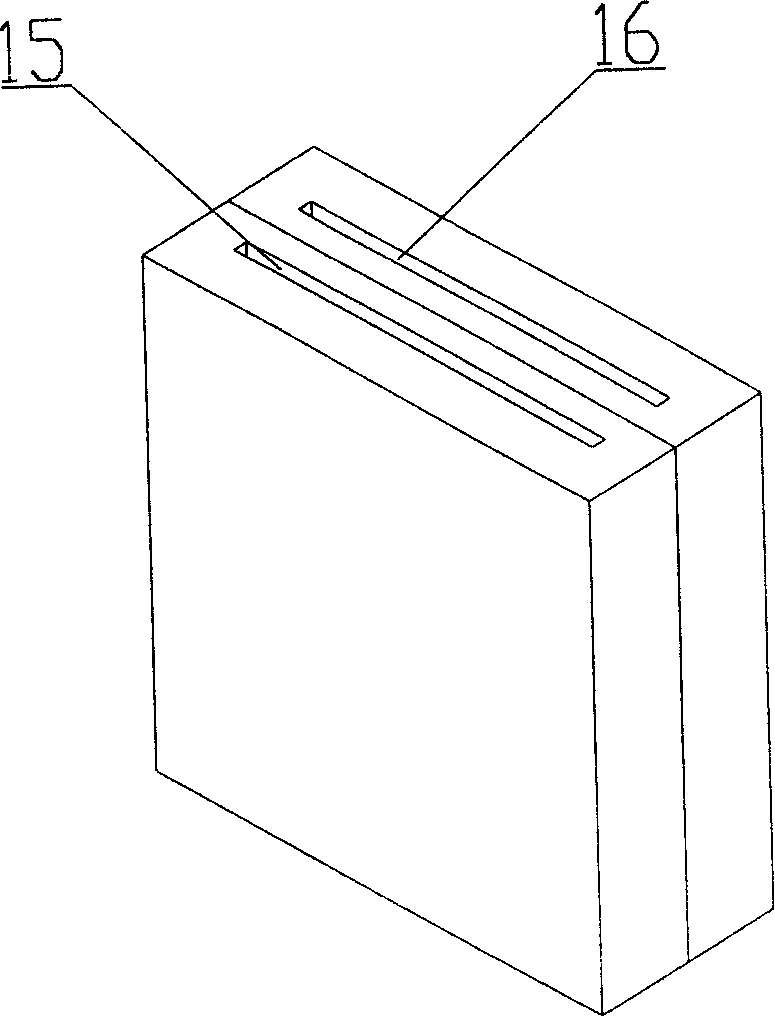
[0037] Embodiment 1: as image 3 with Figure 4 As shown, the single-membrane double-cavity double-port synthetic jet actuator of the present invention includes a vibrating membrane 12, a first cavity 13 and a second cavity 14, and between the first cavity 13 and the second cavity 14 Separated by the vibrating membrane 12 to form independent cavities, the first cavity 13 and the second cavity 14 are respectively provided with a first outlet 15 and a second outlet 16 . Wherein, the vibration drive of the vibrating membrane 12 can be any one of piezoelectric, ferroelectric, electromagnetic, electrostatic, piston and other driving methods, the material of the vibrating membrane 12 can be elastic material, flexible material or composite material, and the shape of the vibrating membrane 12 It can be designed in any shape as required, such as circular or rectangular; the first cavity 13 and the second cavity 14 can be designed in any shape as required and the shape of the vibrating...
Embodiment 2
[0039] Embodiment 2: as Image 6 As shown, in this embodiment, on the basis of Embodiment 1, a flow regulating slider 18 is added between the first outlet 15 and the second outlet 16 . The flow regulating slider 18 can adopt different configurations, such as a boss shape, a trapezoid, a prism, a rectangle or other irregular shapes, and the material of the flow regulating slider 18 is a non-flexible hard material, which is suitable for using micro Manufactured with materials and processes compatible with micro-mechanical technology, the flow regulating slider 18 is located between the first outlet 15 and the second outlet 16 of the actuator, and can slide left and right along the horizontal direction under control.
[0040] Working principle: when the flow adjustment slider 18 slides to the first outlet 15 on the left, see Image 6 , the outlet area of the first outlet 15 decreases, and the area of the second outlet 16 increases accordingly. Under the condition of constant...
Embodiment 3
[0041] Embodiment 3: as Figure 7 As shown, the structure of this embodiment is basically the same as that of Embodiment 2, the difference is that the configuration of the flow regulation slider 18 is different, and its structure and working principle are shown as Figure 7 shown. Flow regulation slide block 18 can adopt different configurations, take boss configuration as example (as Figure 7 ), its working principle is: use the blocking effect of the boss to reduce the mutual entrainment and offset effect of the two adjacent jets at the outlet 15 and 16 and impel it to entrain more fluid around it, and use the Coanda effect of the jet to pass through the boss Guiding the fusion of two adjacent jets makes the synthetic jet 17 wider and more energetic. The working parameters of the exciter in embodiment 3 are the same as those in embodiment 1. Figure 11 The synthetic jet 17 velocity vector diagram is used for the single-membrane, double-cavity, and double-port synthetic j...
PUM
 Abstract
Description
Claims
Application Information