Optical image stabilizer using gimballed prism

An image sensor and prism technology, applied in the field of optical image stabilizers, can solve the problems of complex actuator mechanism, high price, large size, etc.

Inactive Publication Date: 2009-04-01
NOKIA CORP
View PDF0 Cites 42 Cited by
  • Summary
  • Abstract
  • Description
  • Claims
  • Application Information

AI Technical Summary

Problems solved by technology

Actuator mechanisms are often complex, which means they are expensive and large in size

Method used


Image

  • Optical image stabilizer using gimballed prism
  • Optical image stabilizer using gimballed prism
  • Optical image stabilizer using gimballed prism

Examples


Embodiment Construction

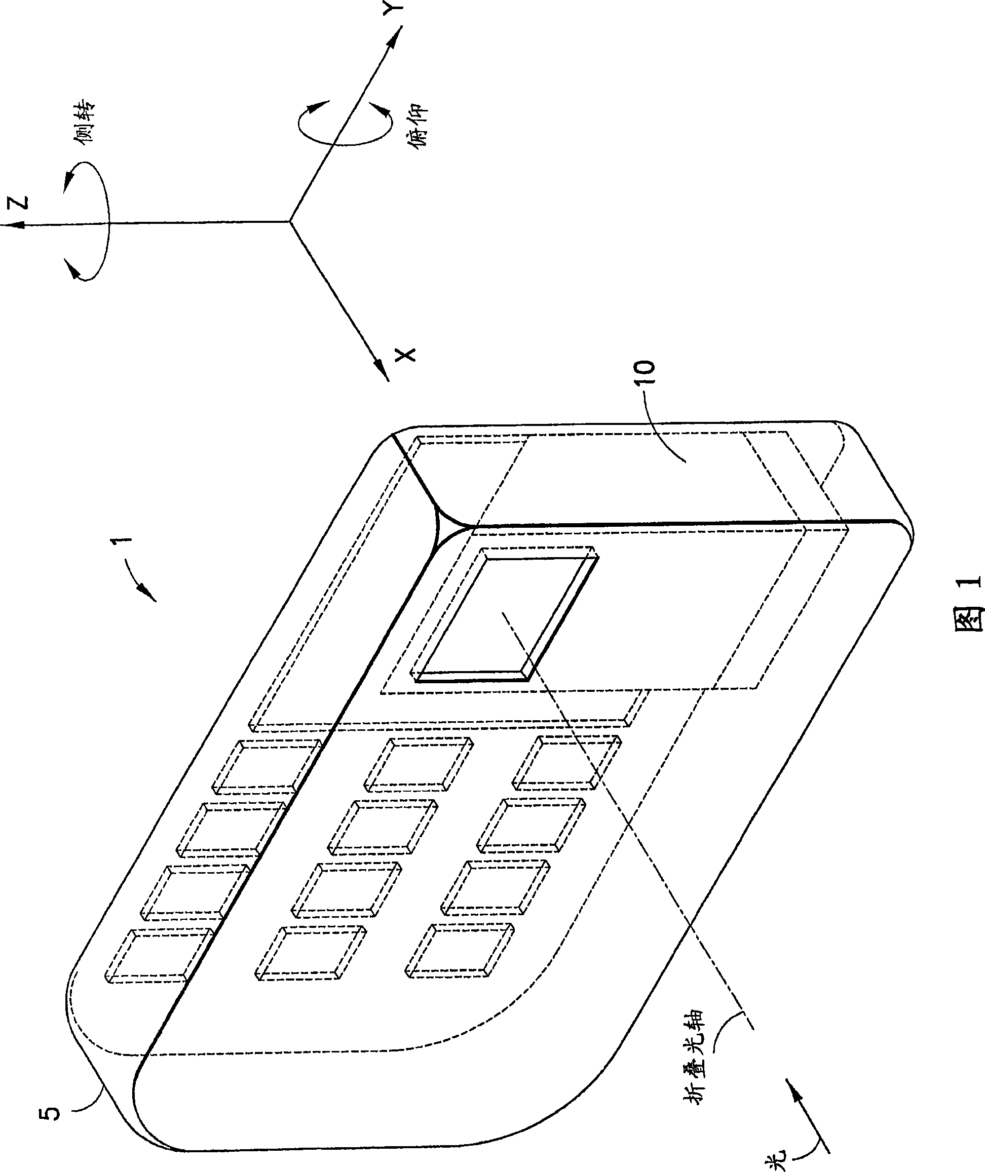
[0048] In an imaging system having an image sensor and a lens to project an image along an optical axis onto the image sensor, the present invention uses a prism to fold the optical axis. Implementing imaging systems with folded optics is particularly useful in thin electronic devices such as mobile phones. Figure 1 is a schematic representation of a camera phone with folded optics.

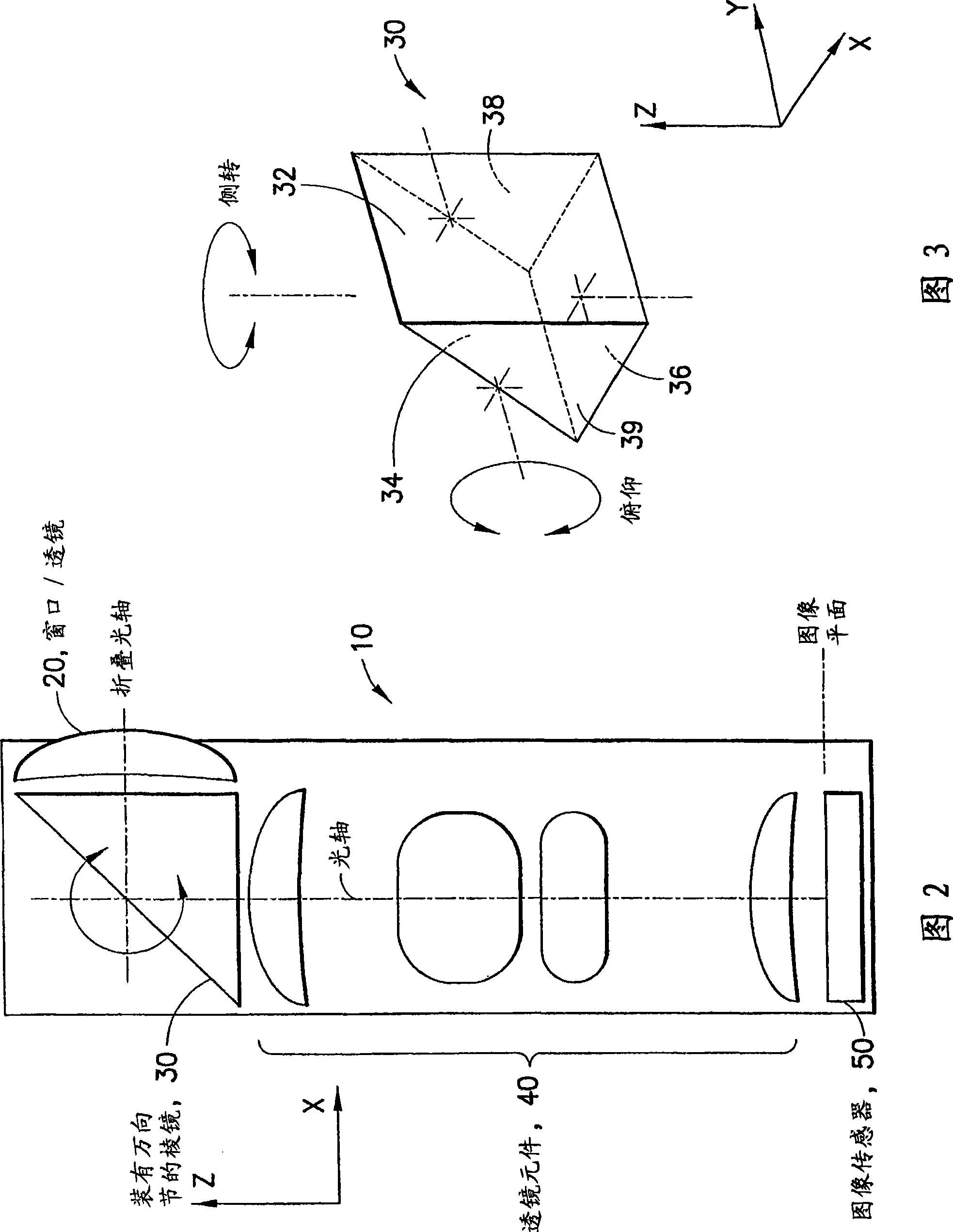
[0049] As shown in Figure 1, the mobile phone 1 has a camera or imaging system 10 to allow a user to take pictures using the imaging system. As shown in FIGS. 1 and 2 , the optical axis of the imaging system 10 that is substantially parallel to the Z axis is folded such that the folded optical axis is substantially parallel to the X axis. As shown in FIG. 2 , the imaging system 10 includes an image sensor 50 , a front lens or window 20 , a prism 30 and possibly a number of other lens elements 40 located on an image plane. When a user takes a picture with a camera phone such as the mobile phone ...


PUM


Abstract

An optical image stabilizer is used to compensate for an unwanted movement of an imaging system, such as a camera. The camera has a folded optics system using a triangular prism to fold the optical axis. Two actuators are used to rotate the prism around two axes in order to compensate for the yaw motion and pitch motion of the camera. The prism can be mounted on a gimballed system or joint and two actuators are operatively connected to the gimballed system in order to rotate the prism. Alternatively, the folded optics system uses a mirror to fold the optical axis, and two motors are used to rotate the prism.

Description

technical field [0001] The present invention relates generally to an imaging system, and more particularly to an optical image stabilizer for use in an imaging system. Background technique [0002] The problem of image stabilization dates back to the beginnings of photography, and the problem involves the fact that image sensors need enough exposure time to form a reasonably good image. Any movement of the camera during the exposure time will cause a shift in the image projected on the image sensor, resulting in a degradation of the quality of the formed image. The quality degradation associated with motion is called motion blur. Holding the camera with one or two hands while taking pictures, it is almost impossible to avoid undesired camera motion during relatively long exposure times. Motion blur is especially prone to occur when the camera is set to a high zoom ratio, where even small movements can significantly degrade the quality of the resulting image. [0003] Opti...

Claims


Application Information

Patent Timeline
Patent Type & Authority Applications(China)
IPC IPC(8): G02B27/64
CPCG03B2205/0023G03B17/17G03B5/00G03B2205/0007H04N1/00307H04N5/2254H04N5/23287G02B27/646H04N5/23248H04N5/23258H04N23/55H04N23/68H04N23/6812H04N23/687
Inventor J·鲁维南P·科阿南
Owner NOKIA CORP
Why Eureka
Try Eureka