Image sensing apparatus, image sensing system and focus detection method

a technology of image sensing and image sensing, which is applied in the direction of camera focusing arrangement, printers, instruments, etc., can solve the problems of not being able to improve accuracy, not being able to set a wide focus detection region, and not being able to adjust the speed of high-speed focus adjustment operations

Inactive Publication Date: 2010-02-25
CANON KK
View PDF23 Cites 195 Cited by
  • Summary
  • Abstract
  • Description
  • Claims
  • Application Information

AI Technical Summary

Benefits of technology

[0017]Further, according to the present invention, a focus detection method in an image sensing apparatus, the method comprises the steps of: performing photoelectric conversion on each pair of light beams that have passed through different regions of a photographing lens and outputting an image signal pair by a plurality of focus detection pixel pairs included in an image sensor; acquiring shift information on relative shift between an op

Problems solved by technology

However, the contrast detection method, also called a hill-climbing detection method, is not suitable for high-speed focus adjustment operations because it is necessary to find an evaluation value while slightly moving the photographing lens, and to keep the photographing lens moving until the evaluation value is deemed to have reached a maximum.
However, in order to perform focus detection using the phase-difference detection method, it is necessary to set the focus detection optical system such that the two divided light beams will not be vignetted even when a change in the exit pupil or image height of the photographing lens, a change in the zoom position, or the like, occurs.
Consequently, there are problems such as not being able to set a wide focus detection region, not being able to improve the accuracy of two divided light beams by base-line length extension, and so on.
However, Japanese Patents Laid-Open Nos. 03-214133 and 2000-156823 have the following problems.
However, the degree of vignetting varies according

Method used


Image

  • Image sensing apparatus, image sensing system and focus detection method
  • Image sensing apparatus, image sensing system and focus detection method
  • Image sensing apparatus, image sensing system and focus detection method

Examples


embodiment 1

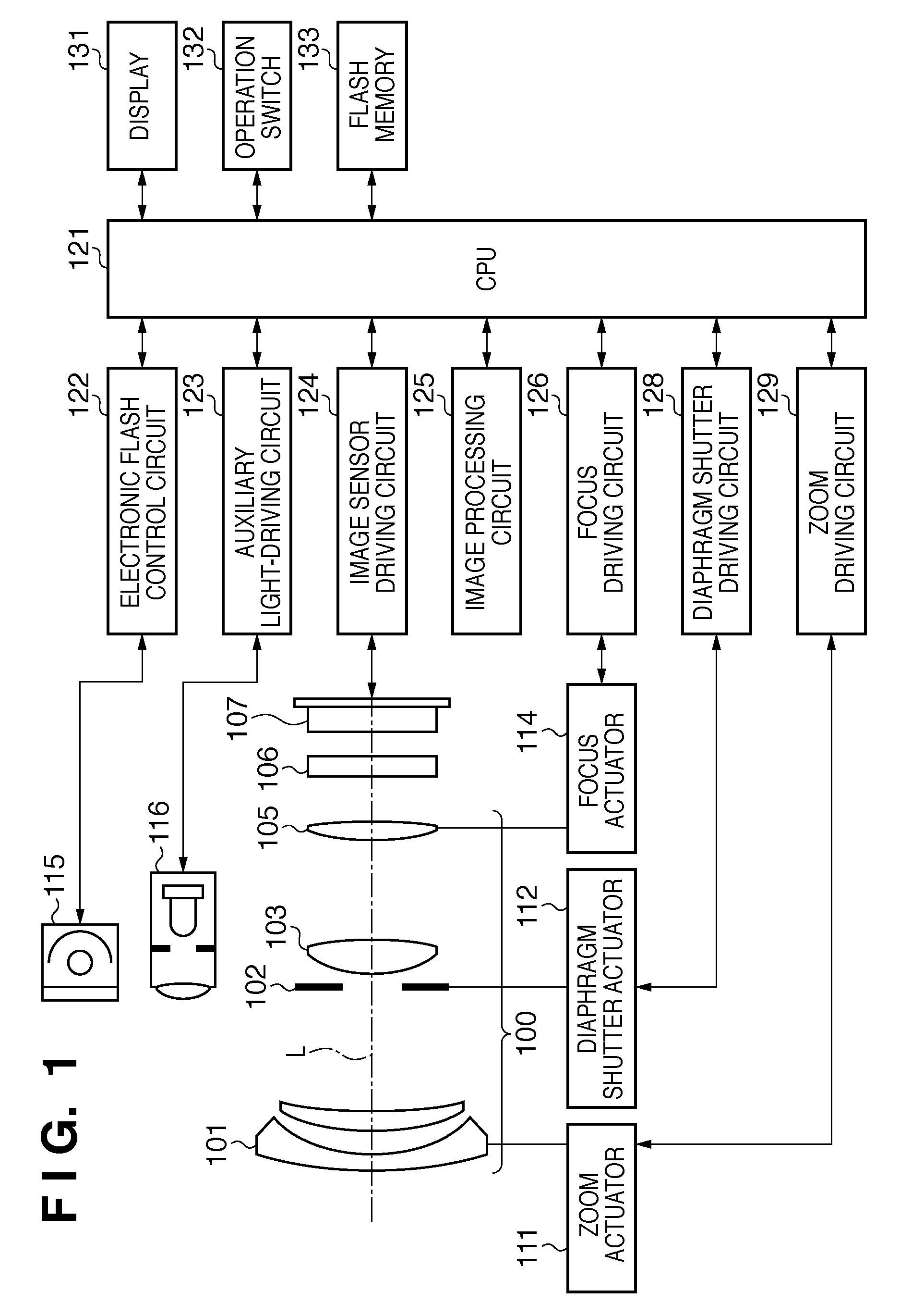
[0045]FIG. 1 is a block diagram showing a configuration of a camera according to Embodiment 1 of the present invention, and shows, as an example, a digital still camera in which a camera body, including an image sensor, and a photographing lens 100 are integrated.

[0046]In FIG. 1, L indicates the optical axis of the photographing lens 100. Reference numeral 101 denotes a first lens group disposed at the front end of the photographing lens 100, and is held so as to be capable of moving back and forth in the optical axis direction. 102 denotes a diaphragm shutter that adjusts the amount of light when photographing by adjusting its aperture diameter and has a function of adjusting an exposure time when photographing a still image. 103 denotes a second lens group. The diaphragm shutter 102 and the second lens group 103 integrally move back and forth in the optical axis direction, and realize a magnification function (zoom function) in conjunction with the back and forth movement of the f...

embodiment 2

[0109]Embodiment 2 of the present invention will be described next.

[0110]Embodiment 2 differs from Embodiment 1 in that Embodiment 2 can cope with the case in which, in the photographing lens 100, the pupil distance changes significantly depending on the zoom or focus position.

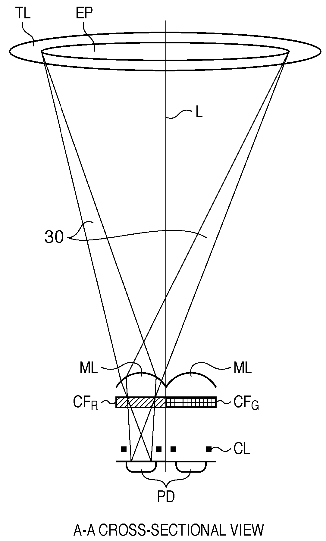
[0111]FIG. 20 is a diagram for illustrating such a case, and shows focus detection pixels that correspond to the focus detection pixels of Embodiment 1 shown in FIG. 11. In FIG. 20, EP1 indicates an exit pupil when the zoom position of the photographing lens 100 is at a telephoto end, and EP2 indicates the exit pupil when the zoom position of the photographing lens 100 is at a wide-angle end. The exit pupil changes in a range indicated by dotted lines in FIG. 20 between the telephoto end and the wide-angle end.

[0112]As described above, in Embodiment 2, not only the diameter of the exit pupil changes according to the zoom position of the photographing lens 100, but also the distance from the microlens to the ex...

embodiment 3

[0118]Embodiment 3 of the present invention will be described next.

[0119]Embodiment 3 shows an example in which the focus detection unit of Embodiment 1 is applied to a camera system.

[0120]FIG. 22 is a block diagram showing a configuration of a camera system according to Embodiment 3. The components indicated by the same reference numerals as those of Embodiment 1 have the same functions, so descriptions thereof are omitted here. In FIG. 22, 220 denotes a camera body, 221 denotes an interchangeable lens detachable from the camera body 220, and they are joined so as to be capable of information communication via I / F units 222 and 223. The interchangeable lens 221 includes a CPU 224 that performs various computation processes, and that is connected to a driving circuit 225 that drives the zoom, focus, diaphragm shutter and the like of the photographing lens 100. The driving circuit 225 is connected to an actuator 226. Furthermore, as in the camera body 220, a flash memory 227 into whi...


PUM


Abstract

An image sensing apparatus including: an image sensor including a plurality of focus detection pixel pairs that perform photoelectric conversion on each pair of light beams that have passed through different regions of a photographing lens and output an image signal pair; a flash memory that stores shift information on relative shift between an optical axis of the photographing lens and a central axis of the focus detection pixel pairs; a correction unit that corrects a signal level of the image signal pair based on the shift information and exit pupil information of the photographing lens so as to compensate for an unbalanced amount of light that enters each of the focus detection pixel pairs; and a focus detection unit that detects a focus of the photographing lens using the image signal pair corrected by the correction unit.

Description

BACKGROUND OF THE INVENTION[0001]1. Field of the Invention[0002]The present invention relates to an image sensing apparatus, an image sensing system, and a focus detection method and, more particularly, to an image sensing apparatus such as a digital still camera, a video camera and a silver-halide camera, an image sensing system, and a focus detection method.[0003]2. Description of the Related Art[0004]A contrast detection method and a phase-difference detection method are used as general methods that employ light beams that have passed through a photographing lens in focus detection and the adjustment of an image sensing device. The contrast detection method is often used in video cameras and digital still cameras, in which an image sensor is used as a focus detection sensor. This method pays attention to the output signal of the image sensor, in particular, information on a high-frequency component (contrast information), and information on the position of the photographing lens ...

Claims


Application Information

Patent Timeline
IPC IPC(8): H04N5/232G03B13/22
CPCG03B3/10H04N5/3696H04N5/23212G03B13/34H04N23/672H04N23/633H04N25/704G02B7/343G02B7/346
Inventor YAMASAKI, RYO
Owner CANON KK
Why Eureka
Try Eureka