Compact light-mixing LED light engine and white LED lamp with narrow beam and high cri using same

a led light engine and led light technology, applied in the field of illumination arts, lighting arts, solid-state lighting arts, can solve the problems of poor efficacy, relatively short lamp life, and reduced response time cos

Active Publication Date: 2011-07-14
SAVANT TECH LLC
View PDF30 Cites 195 Cited by
  • Summary
  • Abstract
  • Description
  • Claims
  • Application Information

AI Technical Summary

Problems solved by technology

These lamps have fast response time, output high light intensity, and have good CRI characteristics, especially for saturated red (e.g., the R9 CRI parameter), but suffer from poor efficacy and relatively short lamp life.
For still higher intensities, high intensity discharge (HID) lamps are used, at the cost of reduced response time due to the need to heat the liquid and solid dose during the warm-up phase after turning on the lamp, and typically also reduced color quality, higher cost, and moderate lamp life ˜10 k-20 k hours.
The undesirable characteristics include: poor efficacy; short life; excessive heat generation; and high life-cycle operating cost.
For MR / PAR / R spot light applications, LED device technologies have been less than satisfactory in replacing incandescent and halogen lamps.
It has been difficult using LED device technologies to simultaneously achieve a combination of both good color and good beam control for spot lamps.
However, these lamps have CRI characteristics corresponding to that of the white LEDs, which is unsatisfactory in some applications.
For example, such LED devices typically produce R9 values of less than 30, and CRI ˜80-85 (where a value of 100 is ideal) which is unacceptable for spot light applications such as product displays, theater and museum lighting, restaurant and residential lighting, and so forth.
Lamps based on this technology have provided good CRI characteristics, but have not produced spot lighting due to large beam FWHM values, typically of order 100° or higher.
However, as noted in Harbers et al. the compound parabolic concentrator design tends to be tall.
This could be problematic for an MR or PAR lamp which has a specified maximum length imposed by the MR / PAR / R regulatory standard to ensure compatibility with existing MR / PAR / R lamp sockets.
However, this approach can compromise color-mixing and hence the CRI characteristics, and also may adversely affect optical coupling with the compound parabolic concentrator, since the number of times that each light ray bounces on the side wall and becomes mixed in color and in spatial distribution is greatly reduced.

Method used


Image

  • Compact light-mixing LED light engine and white LED lamp with narrow beam and high cri using same
  • Compact light-mixing LED light engine and white LED lamp with narrow beam and high cri using same
  • Compact light-mixing LED light engine and white LED lamp with narrow beam and high cri using same

Examples


Embodiment Construction

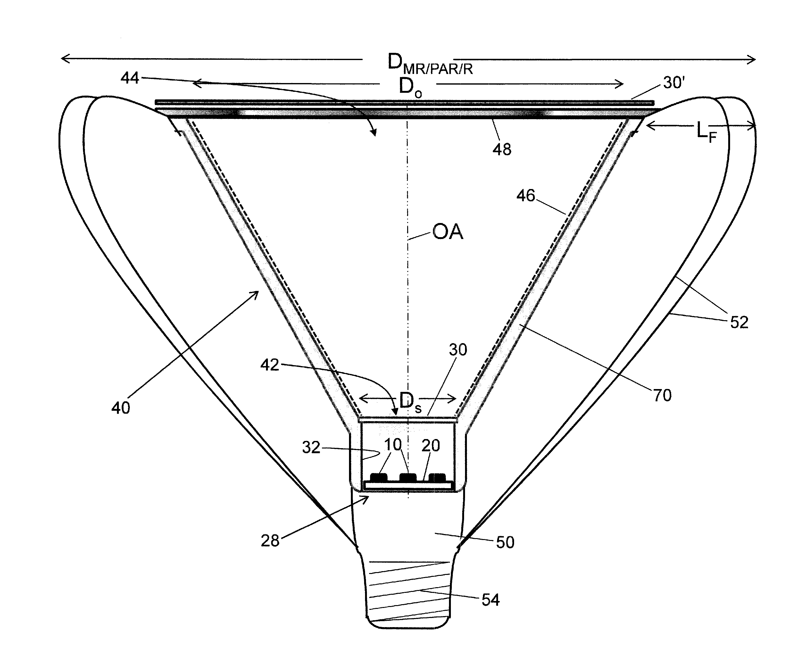
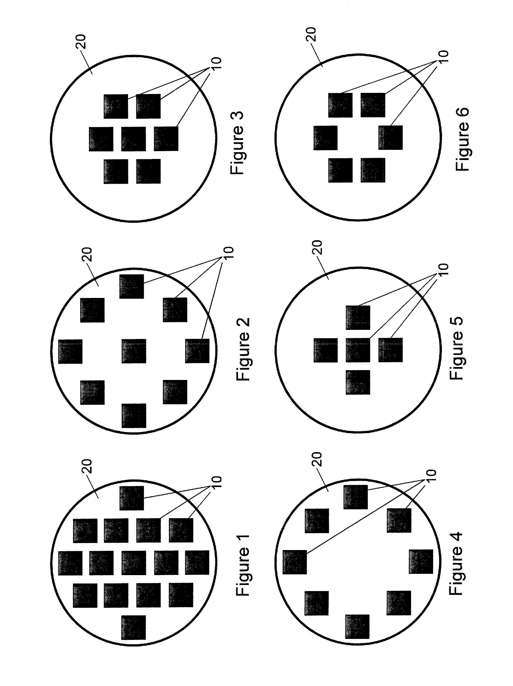
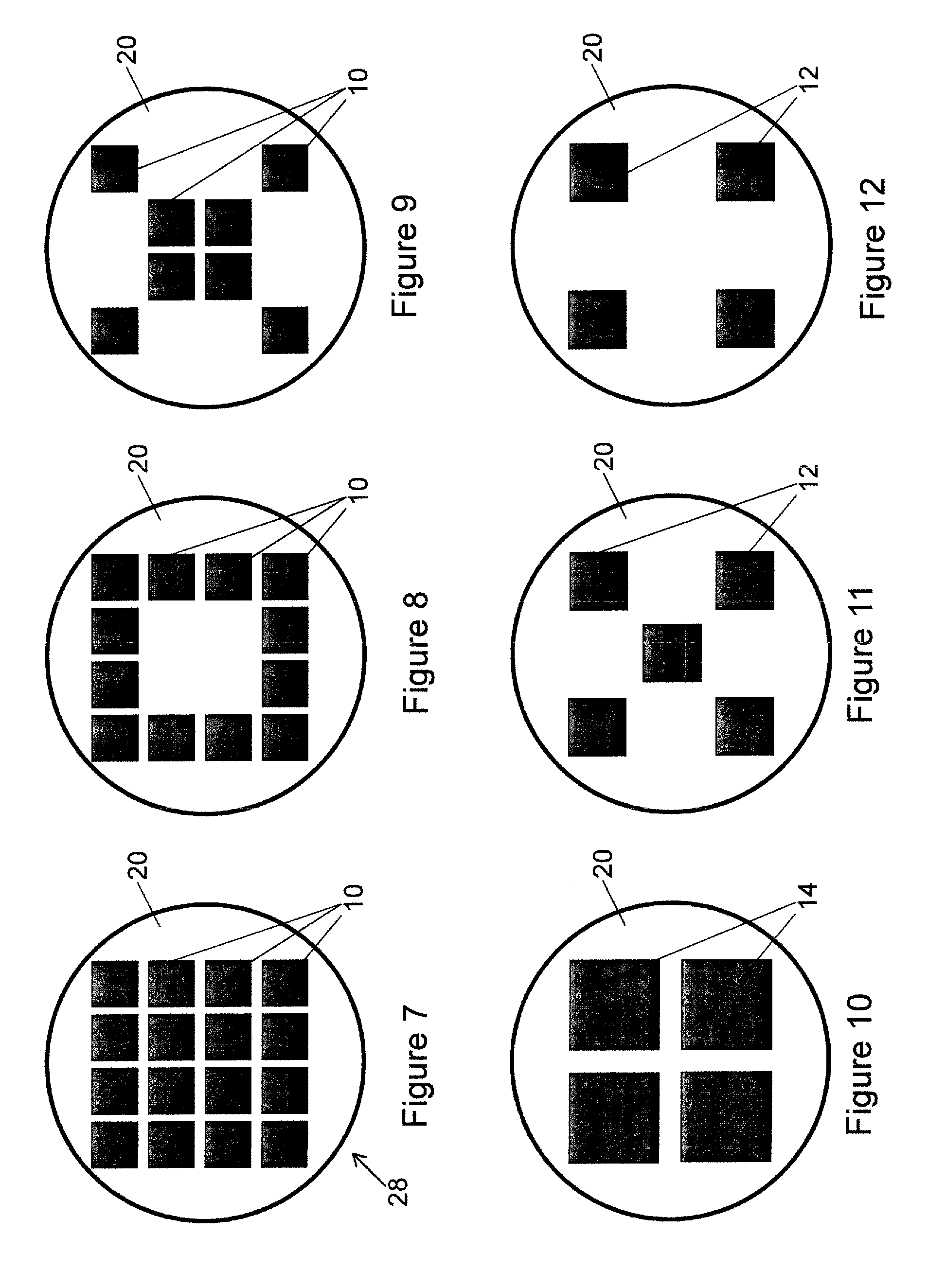
[0025]Disclosed herein is an approach for designing LED based spot lights, which provides a flexible design paradigm capable of satisfying the myriad design parameters of a family of MR / PAR / R lamps or compact LED modules that enable improved optical and thermal access to the light engine. The spot lights disclosed herein employ a low profile LED-based light source optically coupled with beam forming optics. The low profile LED-based light source typically includes one or more LED devices disposed on a circuit board or other support, optionally disposed inside a low-profile light-mixing cavity. In some embodiments, a light diffuser is disposed at the exit aperture of the light-mixing cavity. In some embodiments the light diffuser is disposed in close proximity to the LED array wherein the low profile LED-based light source is sometimes referred to herein as a pillbox, wherein the circuit board supporting the LED devices is a “bottom” of the pillbox, the light diffuser at the exit ape...


PUM


Abstract

A directional lamp comprises a light source, a beam forming optical system configured to form light from the light source into a light beam, and a light mixing diffuser arranged to diffuse the light beam. The light source, beam forming optical system, and light mixing diffuser are secured together as a unitary lamp. The beam forming optical system includes: a collecting reflector having an entrance aperture receiving light from the light source and an exit aperture that is larger than the entrance aperture, and a lens disposed at the exit aperture of the collecting reflector, the light source being positioned along an optical axis of the beam forming optical system at a distance from the lens that is within plus or minus ten percent of a focal length of the lens.

Description

BACKGROUND[0001]The following relates to the illumination arts, lighting arts, solid state lighting arts, and related arts.[0002]Incandescent and halogen lamps are conventionally used as both omni-directional and directional light sources. A directional lamp is defined by the US Department of Energy in its Energy Star Eligibility Criteria for Integral LED Lamps, draft 3, as a lamp having at least 80% of its light output within a cone angle of 120 degrees (full-width at half-maximum of intensity, FWHM). They may have either broad beam patterns (flood lamps) or narrow beam patterns (e.g., spot lamps), for example having a beam intensity distribution characterized by a FWHM <20°, with some lamp standards specified for angles as small as 6-10° FWHM. Incandescent and halogen lamps combine these desirable beam characteristics with high color rendering index (CRI) to provide good light sources for the display of retail merchandise, residential and hospitality lighting, art work, etc. Fo...

Claims


Application Information

Patent Timeline
Patent Type & Authority Applications(United States)
IPC IPC(8): F21V1/00F21V7/00
CPCF21V3/00F21V5/04F21V7/00F21K9/137F21Y2101/02F21Y2105/003F21K9/50F21V13/12F21Y2105/12F21Y2105/10F21K9/60F21Y2115/10F21K9/233
Inventor ALLEN, GARY R.WEAVER, JR., STANTON E.MULDER, R. STEPHENDUDIK, DAVID C.KAMINSKI, MARK E.
Owner SAVANT TECH LLC
Why Eureka
Try Eureka