Electronic endoscope

a technology of endoscope and endoscope, which is applied in the field of electronic endoscope, can solve the problems of excessive distortion, inability to reproduce the proper colors, and the diameter of the rear lens unit must be enlarged, so as to prevent shading and improve distortion.

Inactive Publication Date: 2002-11-05
OLYMPUS OPTICAL CO LTD
View PDF17 Cites 220 Cited by
  • Summary
  • Abstract
  • Description
  • Claims
  • Application Information

AI Technical Summary

Benefits of technology

It is, therefore, a primary object of the present invention to provide an electronic endoscope in which distortion is favorably corrected and provision is made to prevent shading.
It is another object of the present invention to provide an electronic endoscope in which the compactness of the objective lens system is intended to minimize the diameter of the insertable section and the length of a rigid portion at the distal end of the endoscope.

Problems solved by technology

Consequently, the problem is raised that off-axis chief rays of light passing through the objective lens system of the electronic endoscope are incident on pixels different from those on which they are naturally expected to be incident and proper colors are not reproduced.
In general, the objective lens system used in the endoscope has a large angle of view so that a wide field can be observed, and hence is exceedingly subject to distortion.
This objective lens system, however, encounters the difficulty that, in order to render emerging light incident normally on the CCD for the purpose of preventing shading, the diameter of the rear lens unit must be enlarged.
However, the endoscope objective set forth in Sho 61-35414 mentioned above, although it is possible to correct for distortion, cannot render all beams of light emerging from this objective incident normally on the CCD, thus bringing about shading.

Method used


Image

  • Electronic endoscope
  • Electronic endoscope
  • Electronic endoscope

Examples


first embodiment

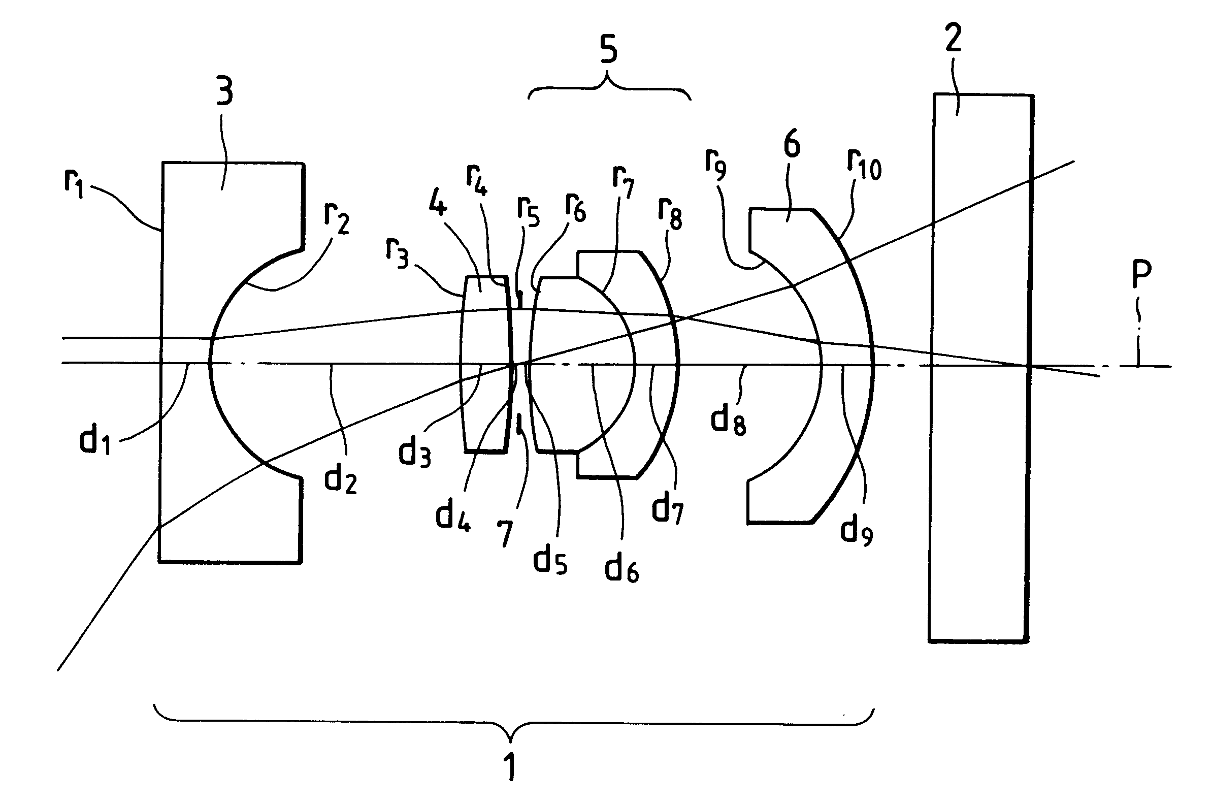
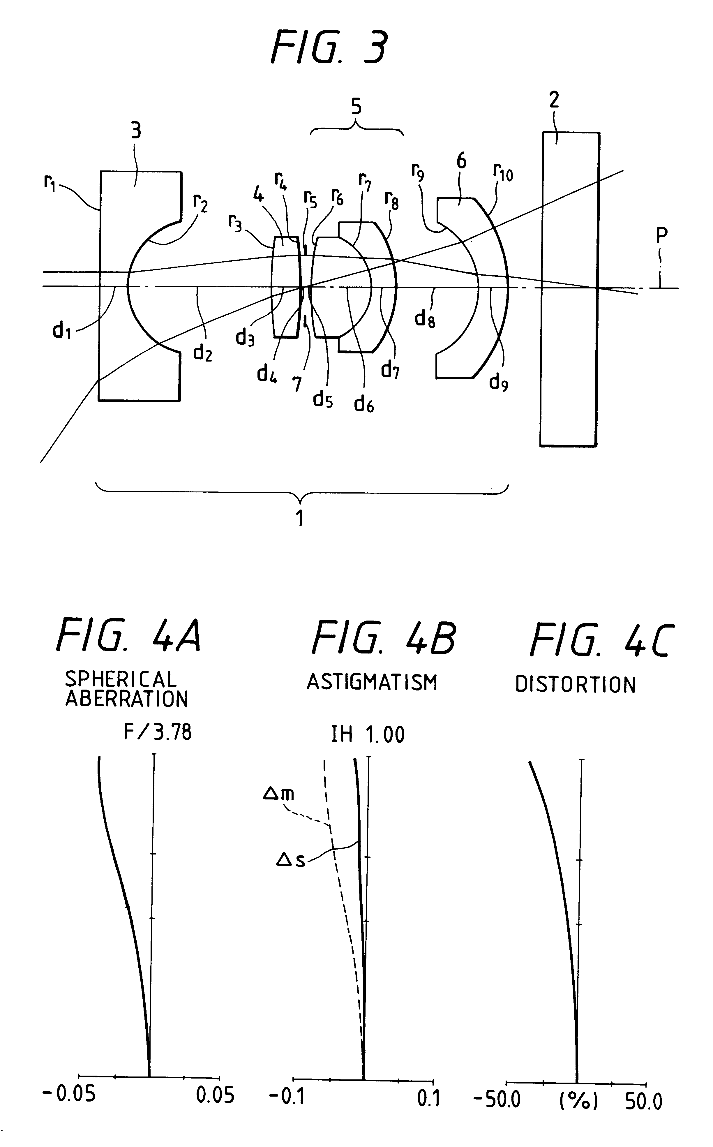
The objective system of the electronic endoscope in this embodiment, as shown in FIG. 3, is constructed with an objective lens system 1 and a CCD 2 which is placed on the light-emergence side thereof. The objective lens system 1 includes, in order from the object side not shown, a first lens unit 3 of a negative lens, a second lens unit 4 of a positive lens, a third lens unit 5 of a positive cemented lens, and a fourth lens unit 6 of a meniscus lens having the concave surface on the object side. An aperture stop 7 is interposed between the second lens unit 4 and the third lens unit 5.

In the electronic endoscope of the first embodiment, the meniscus lens with a concave| surface directed toward the object side is used in the fourth lens unit 6 placed closest to the image side, of lens components constituting the objective lens system 1. It is thus intended to solve the problems that the entire length is increased, the lens diameter is enlarged, and considerable distortion is produced ...

second embodiment

In this embodiment, for the purpose of further reducing the entire length of the objective system, the objective lens system is constructed with three lens components by eliminating the field lens. he objective system of the electronic endoscope of the second embodiment, as shown in FIG. 16, comprises an objective lens system 10 and the CCD 2 placed on the light-emergence side thereof. The objective lens system 10 includes, in order from the object side, a first lens unit 11 of a negative lens, a second lens unit 12 of a positive lens, and a third lens unit 13 of a positive lens. Between the first lens unit 11 and the second lens unit 12, an infrared cutoff filter or laser cutoff filter 14 is interposed, when necessary. An aperture stop 15 is provided on the light-incidence surface of the third lens unit 13. The CCD 2 is the same as that used in the electronic endoscope of the first embodiment which has the function of prevention of shading.

The electronic endoscope of the second emb...

third embodiment

In any endoscope, not to speak of the electronic endoscope, its elongated insertable section must be inserted in a narrow tubular cavity or human body, and hence it is desired to minimize the diameter of the insertable section. Additionally, in order to facilitate the insertion thereof for a bent part and relieve pain caused to a patient in the endoscope for medicine, it is also desired to reduce the length of the rigid portion at the distal end of the insertable section.

To meet these demands, the electronic endoscope, in particular, requires a more compact design of a solid-state imager disposed at the distal end or ocular section thereof, that is, compactness of the CCD. However, the compactness of the CCD causes its pixel size to be diminished and makes the area of the photosensor section of the CCD small. Consequently, the problem is encountered that the amount of light which is necessary for entering the image area of the CCD to form an object image is decreased and the output ...


PUM


Abstract

An electronic endoscope includes an objective lens system in which chief rays directed toward the maximum image height are inclined outwardly with respect to the optical axis and a solid-state image sensor which has a light-receiving surface on which many pixels are arrayed and which provides a light beam inclined outwardly with respect to the optical axis and incident on the light-receiving surface with a higher power, in separating from the center of the light-receiving surface, than a light beam incident perpendicularly on the light-receiving surface. In doing so, distortion is favorably corrected and shading can be prevented.

Description

BACKGROUND OF THE INVENTION1. Field of the InventionThis invention relates to an electronic endoscope in which provisions are made to correct for distortion and prevent shading.2. Description of Related ArtIn recent years, An endoscope whose elongated, insertable section is inserted in a narrow tubular cavity or human body to observe an organ has come into prominent use. In particular, an electronic endoscope is often used in which a solid-state image sensor, such as a CCD (charge coupled device), is placed at the distal end or ocular section of the endoscope so that observations can be made through a monitor.In keeping with an increase of the number of pixels arrayed on the light-receiving surface of the CCD, a compact design of the CCD has recently been developed. Consequently, the problem is raised that off-axis chief rays of light passing through the objective lens system of the electronic endoscope are incident on pixels different from those on which they are naturally expected...

Claims


Application Information

Patent Timeline
Patent Type & Authority Patents(United States)
IPC IPC(8): A61B1/05G02B23/24H04N5/217H04N5/225A61B1/04G02B9/00G02B23/26
CPCA61B1/00096A61B1/00101A61B1/05A61B1/051G02B9/12G02B9/34G02B23/243G02B23/2484H04N5/217H04N2005/2255H04N23/81H04N23/555
Inventor NAKAMURA, SHINICHI
Owner OLYMPUS OPTICAL CO LTD
Why Eureka
Try Eureka