Intermediate telephoto lens system

a telephoto lens and coma technology, applied in the field of telephoto lens systems, can solve the problems of gauss-type lens systems that are not suitable for forming telephoto lens systems, unable to have symmetry in the ernostar-type lens system, and not suitable for spherical aberration and coma correction, so as to facilitate the formation of telephoto-type lens systems, the effect of correcting astigmatism and distortion

Inactive Publication Date: 2007-10-04
RICOH IMAGING COMPANY
View PDF11 Cites 66 Cited by
  • Summary
  • Abstract
  • Description
  • Claims
  • Application Information

AI Technical Summary

Benefits of technology

[0012]As an advantage of the Ernostar type lens system, it is easier to form a telephoto-type lens system, miniaturization of the lens system is attained, and the correcting of spherical aberration and coma is suitably made. On the other hand, an Ernostar-type lens system does not have symmetry regarding a lens arrangement, and is not suitable for the correcting of astigmatism and distortion in the case where the Ernostar-type lens system has a larger angle-of-view.
[0013]As an advantage of the Gauss type lens system, symmetry regarding a lens arrangement is suitably maintained, and the correcting of astigmatism and distortion is suitably made. However, a Gauss-type lens system is not suitable for forming a telephoto lens system.

Problems solved by technology

On the other hand, an Ernostar-type lens system does not have symmetry regarding a lens arrangement, and is not suitable for the correcting of astigmatism and distortion in the case where the Ernostar-type lens system has a larger angle-of-view.
However, a Gauss-type lens system is not suitable for forming a telephoto lens system.

Method used


Image

  • Intermediate telephoto lens system
  • Intermediate telephoto lens system
  • Intermediate telephoto lens system

Examples


embodiment 1

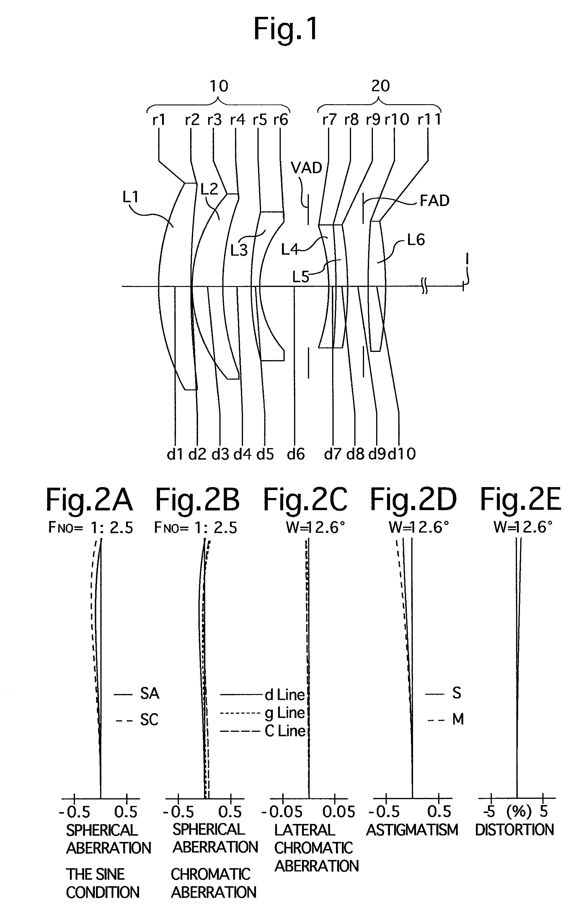
[0086]FIG. 1 is the lens arrangement of the intermediate telephoto lens system, according to the first embodiment of the present invention. FIGS. 2A through 2E show aberrations occurred in the lens arrangement shown in FIG. 1.

[0087]Table 1 shows the numerical data of the first embodiment.

[0088]The positive front lens group 10 includes two positive meniscus lens elements each having the convex surface facing toward the object (the positive first lens element L1 and the positive second lens element L2), and a negative meniscus lens element having the convex surface facing toward the object (the negative third lens element L3), in this order from the object.

[0089]The positive rear lens group 20 includes cemented lens elements having a negative meniscus lens element (the negative fourth lens element L4) having the convex surface facing toward the image and a positive meniscus lens element (the positive fifth lens element L5) having the convex surface facing toward the image, and a bicon...

embodiment 2

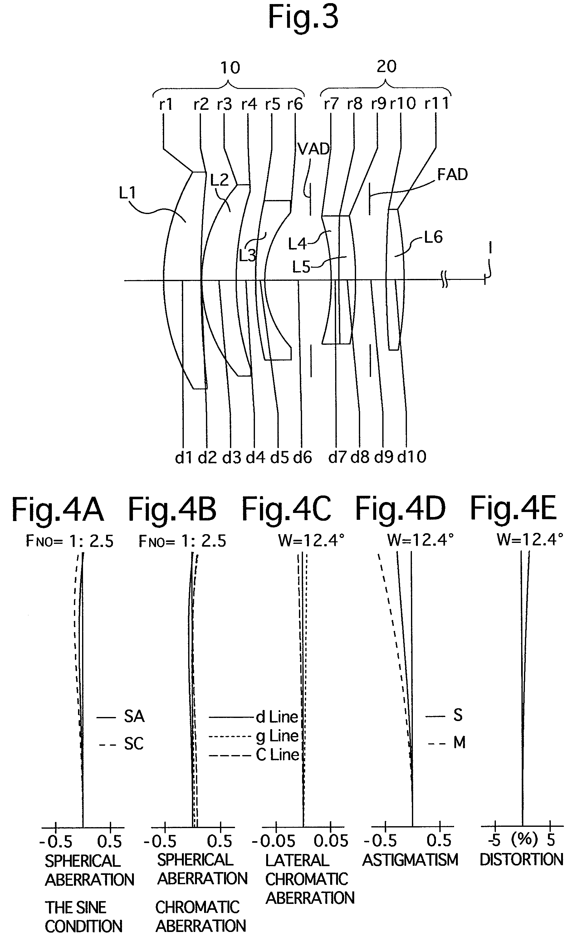
[0092]FIG. 3 is the lens arrangement of the intermediate telephoto lens system, according to the second embodiment of the present invention. FIGS. 4A through 4E show aberrations occurred in the lens arrangement shown in FIG. 3.

[0093]Table 2 shows the numerical data of the second embodiment.

[0094]Except that the negative fourth lens element L4 is constituted by a biconcave lens element, and that the positive fifth lens element L5 is constituted by a biconvex lens element, the basic lens arrangement of the second embodiment is the same as that of the first embodiment.

[0095]The variable-aperture diaphragm VAD is positioned 2.709 in front of (on the object side of) the positive rear lens group 20 (surface No. 7).

[0096]The fixed-aperture diaphragm FAD is positioned 1.0 in front of the positive sixth lens element L6 (surface No. 10).

TABLE 2FNO. = 1:2.5f = 68.61W = 12.4fB = 37.82Surf. No.rdNdν127.5924.791.6980055.42128.8000.10318.8644.351.7000052.8437.5752.43547.5681.151.8050027.4612.9538....

embodiment 3

[0097]FIG. 5 is the lens arrangement of the intermediate telephoto lens system, according to the third embodiment of the present invention. FIGS. 6A through 6E show aberrations occurred in the lens arrangement shown in FIG. 5.

[0098]Table 3 shows the numerical data of the third embodiment.

[0099]The basic lens arrangement of the third embodiment is the same as that of the first embodiment.

[0100]The variable-aperture diaphragm VAD is positioned 2.766 in front of (on the object side) of the positive rear lens group 20 (surface No. 7).

[0101]The fixed-aperture diaphragm FAD is positioned 1.0 in front of the positive sixth lens element L6 (surface No. 10).

TABLE 3FNO. = 1:2.5f = 67.98W = 12.6fB = 37.82Surf. No.rdNdν129.6564.421.6968055.52117.2890.10319.3884.051.6968055.5433.7513.98540.3981.161.7851725.7613.1449.097−24.9051.001.6984032.08−132.2291.781.5281457.89−42.8262.4810107.8272.631.7594028.911−45.857—


PUM


Abstract

An intermediate telephoto lens system includes a positive front lens group, a variable-aperture diaphragm, and a positive rear lens group, in this order from the object.
The positive front lens group includes a positive first lens element L1, a positive second lens element L2 and a negative third lens element L3, in this order from the object.
The positive rear lens group includes cemented lens elements having a negative fourth lens element L4 and a positive fifth lens element L5, and a positive sixth lens element L6, in this order from the object.
The intermediate telephoto lens system satisfies the following condition:
2.0<f/f12<3.0   (1)
    • wherein
    • f designates the focal length of the entire intermediate telephoto lens system; and
    • f12 designates the combined focal length of the positive first lens element L1 and the positive second lens element L2.

Description

BACKGROUND OF THE INVENTION[0001]1. Field of the Invention[0002]The present invention relates to an intermediate telephoto lens system, having an angle-of-view of approximately 25°, for use in a digital single lens reflex (SLR) camera.[0003]2. Description of the Prior Art[0004]An intermediate telephoto lens system has generally been defined as a lens system having a focal-length range from 75 mm to 135 mm with respect to the 135 (35 mm) film format.[0005]Particularly, an intermediate telephoto lens system with an angle-of-view of 25° (equivalent to a focal length of a little more than 100 mm) has a long-lasting demand (popularity) for portrait use with a single focal length; and for use in a digital SLR camera, further miniaturization of an intermediate telephoto lens system in the optical axis direction has been required (i.e., a thinner lens system).[0006]The size of an imaging device for a digital SLR camera is generally smaller than that of a film-frame of the 135 (35 mm) film f...

Claims


Application Information

Patent Timeline
Patent Type & Authority Applications(United States)
IPC IPC(8): G02B13/02
CPCG02B9/60G02B13/005G02B13/02G02B13/0075G02B13/009G02B13/006
Inventor SAORI, MASAKAZU
Owner RICOH IMAGING COMPANY
Why Eureka
Try Eureka