Image processing apparatus and image recording apparatus and image processing method
An image processing equipment, image technology, applied in the direction of image communication, electrical components, etc.
- Summary
- Abstract
- Description
- Claims
- Application Information
AI Technical Summary
Problems solved by technology
Method used
Image
Examples
Embodiment 1
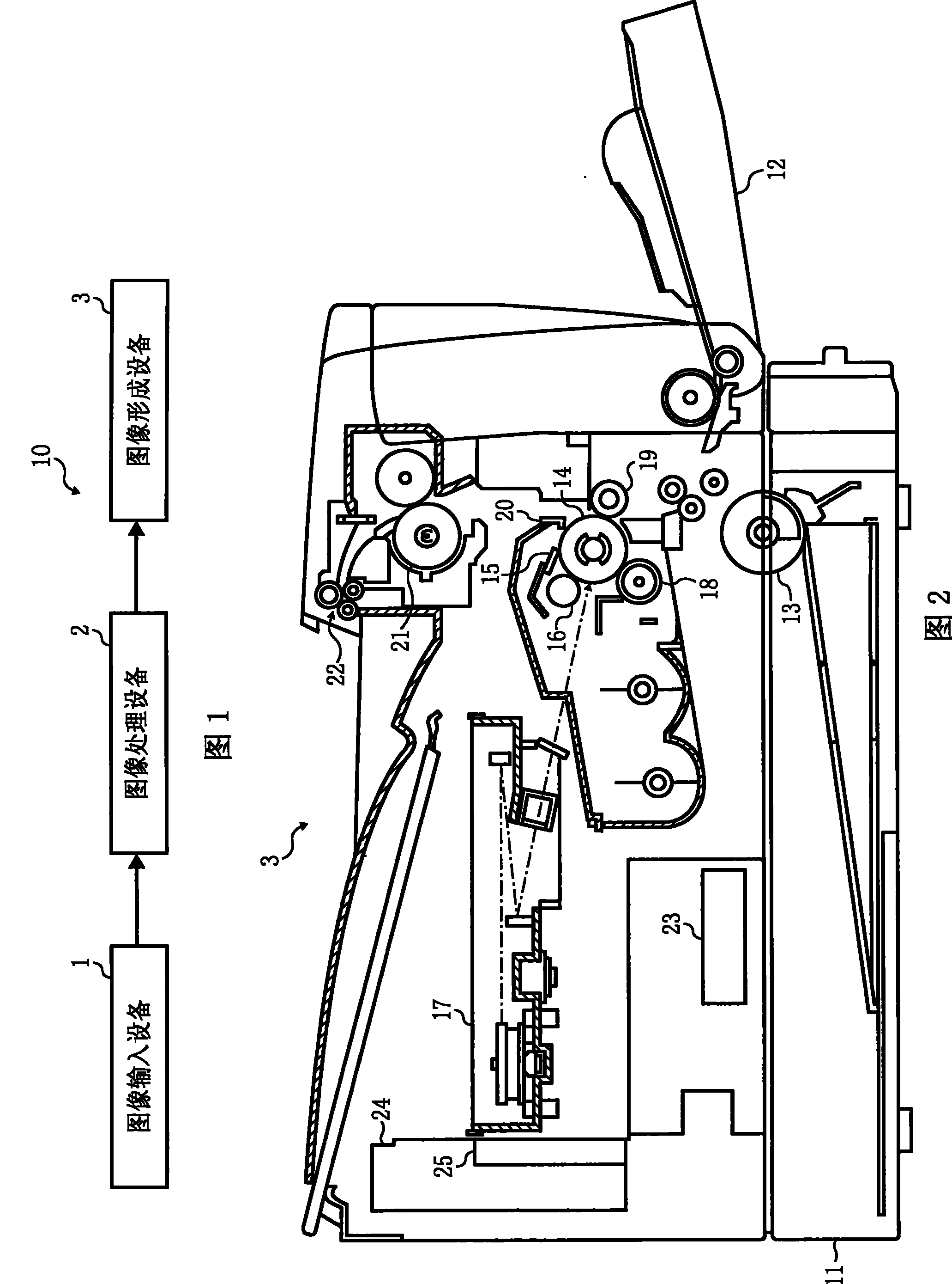
[0054] FIG. 1 shows the structure of an image input and output system 10 composed of an image processing device of the present invention. FIG. 2 shows the structure of the image recording apparatus 3 to which the present invention is applied. FIG. 5 shows the configuration of an image processing apparatus of Embodiment 1 of the present invention. In FIG. 1 , an image input device 1 shows an input device such as a scanner or a digital camera, and an input image is read as image data of 256 gradations with 8-bit precision, for example. This multilevel image data is input to the image processing apparatus 2 of the present invention.
[0055] In the image processing device 2 , the image data of 256 gray scales input from the image input device 1 is converted into gray scales outputtable by the subsequent image recording device (image output device) 3 . In this gradation conversion process, multi-level error diffusion and multi-level average error minimization methods can also be...
Embodiment 2
[0110] FIG. 7 shows the structure of an image processing apparatus of Embodiment 2 of the present invention.
[0111] The input terminal 201 is input with multilevel image data from the image input device 1 . Therefore, in order to represent two-dimensional image data, it is expressed as In(x, y) (x represents an address in the main scanning direction of the image, and y represents an address in the sub scanning direction).
[0112] Then, this input data In(x, y) is input to the adder 202 and the variable threshold setting section 208 . The adder 202 adds the input data In(x, y) and the error component E(x, y) input from the error memory 206, calculates the corrected data C(x, y), and outputs the corrected data C(x, y) to the comparison judgment section 203 and the subtractor 205 .
[0113] Also, input data In(x, y) is input to the variable threshold setting section 208 . In the variable threshold setting section 208, corresponding to Figure 8 Shown input data In (x, y) t...
Embodiment 3
[0136] Figure 9 The structure of the image processing apparatus of Embodiment 3 of the present invention is shown.
[0137] The input terminal 301 is input with multilevel image data from the image input device 1 . Then, the input data In(x, y) is input to the adder 302 . The adder 302 adds the input data In(x, y) and the error component E(x, y) input from the error memory 306, calculates the corrected data C(x, y), and outputs the corrected data C(x, y) to the comparison judgment section 303 and the subtractor 305 .
[0138] The comparison judgment section 303 determines the output value Out(x, y) according to the formula (1) based on the correction data C(x, y) input from the adder 302 and the threshold group T(x, y) input from the threshold setting section 308. ), this Out(x, y) is output from the output terminal 304 to the image recording device 3 .
[0139] Also, the output value Out(x, y) is input to the quantization memory 309 and the subtractor 305 . The subtract...
PUM
 Abstract
Description
Claims
Application Information
 - R&D
- Intellectual Property
- Life Sciences
- Materials
- Tech Scout
- Unparalleled Data Quality
- Higher Quality Content
- 60% Fewer Hallucinations
Browse by: Latest US Patents, China's latest patents, Technical Efficacy Thesaurus, Application Domain, Technology Topic, Popular Technical Reports.
© 2025 PatSnap. All rights reserved.Legal|Privacy policy|Modern Slavery Act Transparency Statement|Sitemap|About US| Contact US: help@patsnap.com


