Device and method for implementing stereo imaging by overall view ring belt imaging lens

An imaging lens and stereoscopic imaging technology, applied in optical components, optics, instruments, etc., can solve the problems of image matching error, heavy weight, complex structure, etc., and achieve the effect of improving relative aperture, simple structure, and high reliability

Active Publication Date: 2009-04-22
ZHEJIANG UNIV
View PDF0 Cites 22 Cited by
  • Summary
  • Abstract
  • Description
  • Claims
  • Application Information

AI Technical Summary

Problems solved by technology

The advantage of this method is that there are no moving parts, and panoramic images can be obtained in real time. However, due to the phenomenon that the 360° annular scene is partially blocked by another panoramic imaging system, it is impossible to obtain complete panoramic stereoscopic imaging information. Two panoramic imaging systems are used simultaneously. system, increasing the weight and complexity of the system
Some foreign and domestic scholars have also proposed a method of using two hyperboloid catadioptric cameras to realize panoramic stereoscopic imaging. Instead of placing them side by side, two panoramic cameras are placed coaxially up and down. However, due to the need for two optical systems and two detectors, Not only is the structure complex and heavy, but there are also image matching errors
[0006] Scholars such as South Korea and Canada have completed the development of a panoramic stereoscopic imaging optical system by using two high-order aspheric mirrors, and proposed an effective solution for realizing panoramic stereoscopic imaging with only one optical system. However, since the optical system is based on a total reflection structure, The mirror size of the system is too large relative to the focal length of the optical system, and the system structure is limited to thin beam imaging, it is difficult to improve the resolution of the optical system, especially in the infrared band, it is difficult to achieve a small F number (that is, a large relative aperture, such as D / F=1) Panoramic Stereoscopic Imaging Optical System That Meets Infrared Detector Requirements

Method used


Image

  • Device and method for implementing stereo imaging by overall view ring belt imaging lens
  • Device and method for implementing stereo imaging by overall view ring belt imaging lens
  • Device and method for implementing stereo imaging by overall view ring belt imaging lens

Examples


Embodiment Construction

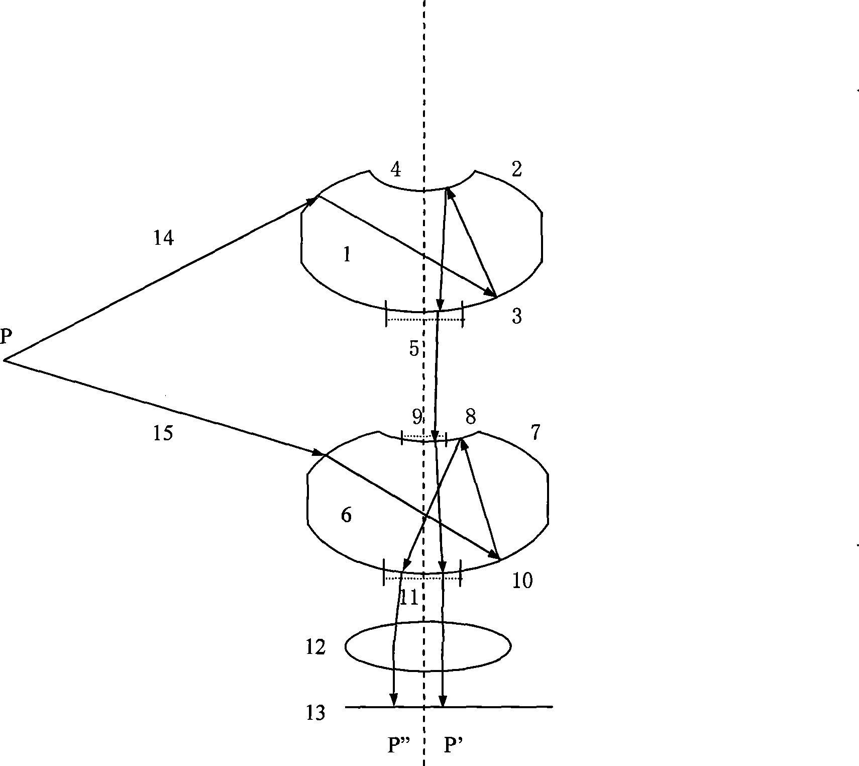
[0016] like figure 1 , 2 As shown, using the panoramic annular imaging lens to realize the stereoscopic imaging device is to be provided with the first panoramic annular imaging lens 1, the second panoramic annular imaging lens 6, the subsequent image transfer lens 12, and the image surface 13 on the same optical axis, One side of the first panoramic annular zone imaging lens 1 is an outwardly protruding annular first refracting surface 2, and the other side is an outwardly protruding annular first reflecting surface 3, and a concave second reflecting surface 4 is provided at the center of the annular first refracting surface. , the inner ring edge of the center of the first annular refraction surface 2 is connected to the edge of the second reflective surface 4, the second refraction surface 5 is arranged at the center of the first annular reflective surface 3, and the inner ring edge of the center of the first annular reflective surface 3 is connected to the second reflecti...


PUM


Abstract

The invention discloses a device using panoramic view zone imaging lenses to realize stereoscopic imaging and a method thereof. The optical line emitted by an object point is formed on the image surface through the first panoramic view zone imaging lens, and the formed image is a first zone; the other optical line emitted by the object point is also formed on the same image surface through the second panoramic view zone imaging lens, and the formed image is a second zone; by changing the curvatures of all the surfaces in the first panoramic view zone imaging lens and all the surfaces in the second panoramic view zone imaging lens, the outside diameter of a first zone is smaller than the inside diameter of a second zone. By utilizing two panoramic view ring-shaped lenses positioned on the same optical axis, the invention forms the image of the same object point in the zone object space on the two noverlapping image points positioned on the same image surface; as the two images points obtain the information of the same object point from different visual angles, the steric information of the object point can be obtained, thus only one optical system can be used for realizing the stereoscopic imaging of panoramic view zone space.

Description

technical field [0001] The invention relates to a lens imaging device and a method thereof, in particular to a stereoscopic imaging device and a method thereof utilizing a panoramic annular band imaging lens. Background technique [0002] Traditional panoramic stereoscopic imaging generally requires two small field of view imaging lenses to be aimed at the same scene to obtain stereoscopic information of the small field of view object, and then rotate the two imaging lenses by 360° at the same time to achieve panoramic stereoscopic imaging. This method requires moving parts and software stitching of stereoscopic images, which has poor reliability; at the same time, it cannot realize instantaneous panoramic stereoscopic imaging. [0003] The panoramic annular imaging technology based on the principle of planar cylindrical projection is a new imaging technology that is completely different from the traditional central projection principle. It can image the surrounding 360° ann...

Claims


Application Information

Patent Timeline
Patent Type & Authority Applications(China)
IPC IPC(8): G02B17/08G02B13/06
Inventor 白剑牛爽侯西云杨国光
Owner ZHEJIANG UNIV
Why Eureka
Try Eureka