
Lighting device for a medical supply unit

A technology for lighting equipment and lamp units, applied in lighting and heating equipment, medical lighting, hospital equipment, etc., can solve the problems of unfavorable patients, speed up the recovery process, unsightly exhaust vents, etc., to reduce costs, improve comfort, The effect of relaxed atmosphere

Inactive Publication Date: 2014-01-08
TRUMPF MEDIZIA SYST GMBH CO KG
View PDF4 Cites 0 Cited by
  • Summary
  • Abstract
  • Description
  • Claims
  • Application Information

AI Technical Summary

Problems solved by technology

For example, a room ceiling may have an unsightly vent, which is not good for the patient and does not speed up the recovery process

Method used


Image

  • Lighting device for a medical supply unit
  • Lighting device for a medical supply unit
  • Lighting device for a medical supply unit

Examples


Embodiment Construction

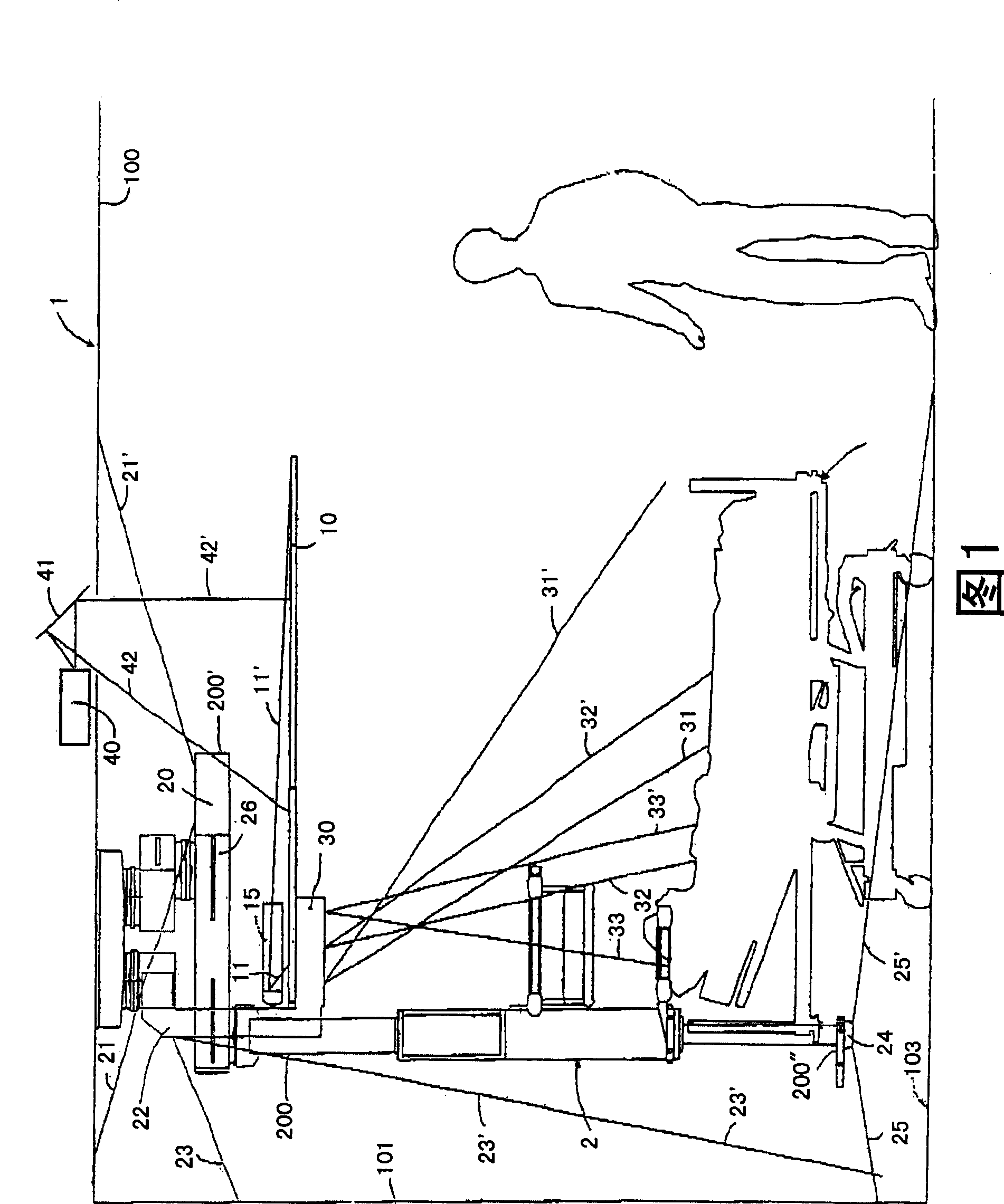
[0019] figure 1 A conceptual diagram showing a lighting device with drawn beams of individual light sources. The lighting device consists of a plurality of light sources fixed to the medical unit via the lighting unit. A medical unit 2 is placed in the room 1 and includes stationary units 200, 200', and 200". Also, a hospital bed 3 is placed in the room 1. The room ceiling 100 includes a recess through which an imaging device such as a projector 40 The light beams 42, 42' can enter the room 1. At the same time, the projector 40 is placed above and parallel to the room ceiling 100. The light beams 42, 42' emitted from the projector 40 are deflected by the mirror 41 so that they pass through the concave Enter room 1 through the mouth.

[0020] Further, the fixing units 200 are fixed to the medical unit 2 and then to the ceiling 100, and they include a plurality of light units, and the room 1 is illuminated with the plurality of light units. Thus, the first lamp unit is dispos...


PUM


Abstract

The device has a light unit and a translucent representation surface arranged on an attachment unit (200), where the translucent representation surface is made of plastic fabric. A light source arranged within the light unit, is aligned with the translucent representation surface. The translucent representation surface is formed in such a manner that lighting of the translucent representation surface and the image projection on the translucent representation surface are enabled. A retaining unit is arranged in the attachment unit.

Description

technical field [0001] The invention relates to a lighting device for a medical unit according to the features of the preamble of claim 1 . Background technique [0002] Most public lighting concepts for lighting rooms mainly consist of direct room lighting and appropriate indirect room lighting, which may preferably be provided in the walls or ceiling rods of the room. Here, the setting of direct and / or indirect room lighting is not suitable for objects in the room, eg hospital beds in a hospital room, so that the patient may be dazzled by the setting of room lighting. [0003] In order to implement room lighting, separate electrical devices and components are also required, which leads to additional work and thus additional costs, especially during renovation or renovation of room lighting. In addition, the line of sight of the sleeping patient in the ward is mainly directed towards the ceiling of the room. For example, a room ceiling may have an unsightly vent, which is...

Claims


Application Information

Patent Timeline
Patent Type & Authority Patents(China)
IPC IPC(8): F21S8/00F21V1/14G09F13/04F21W131/20F21Y101/00
CPCA61M2209/084A61M2021/005F21V33/0068F21V14/00A61M21/00F21W2131/208F21W2131/205
Inventor G·鲍尔J·布伦纳
Owner TRUMPF MEDIZIA SYST GMBH CO KG
Features
  • Generate Ideas
  • Intellectual Property
  • Life Sciences
  • Materials
  • Tech Scout
  • Unparalleled Data Quality
  • Higher Quality Content
  • 60% Fewer Hallucinations
Learn More