Security element with an optically variable structure
An anti-counterfeiting component and variable technology, applied in the direction of printing, printing, printing devices, etc. for the production of special varieties of printed matter
- Summary
- Abstract
- Description
- Claims
- Application Information
AI Technical Summary
Problems solved by technology
Method used
Image
Examples
example 1
[0103] example 1( Figure 2 to Figure 4 and Figure 34)
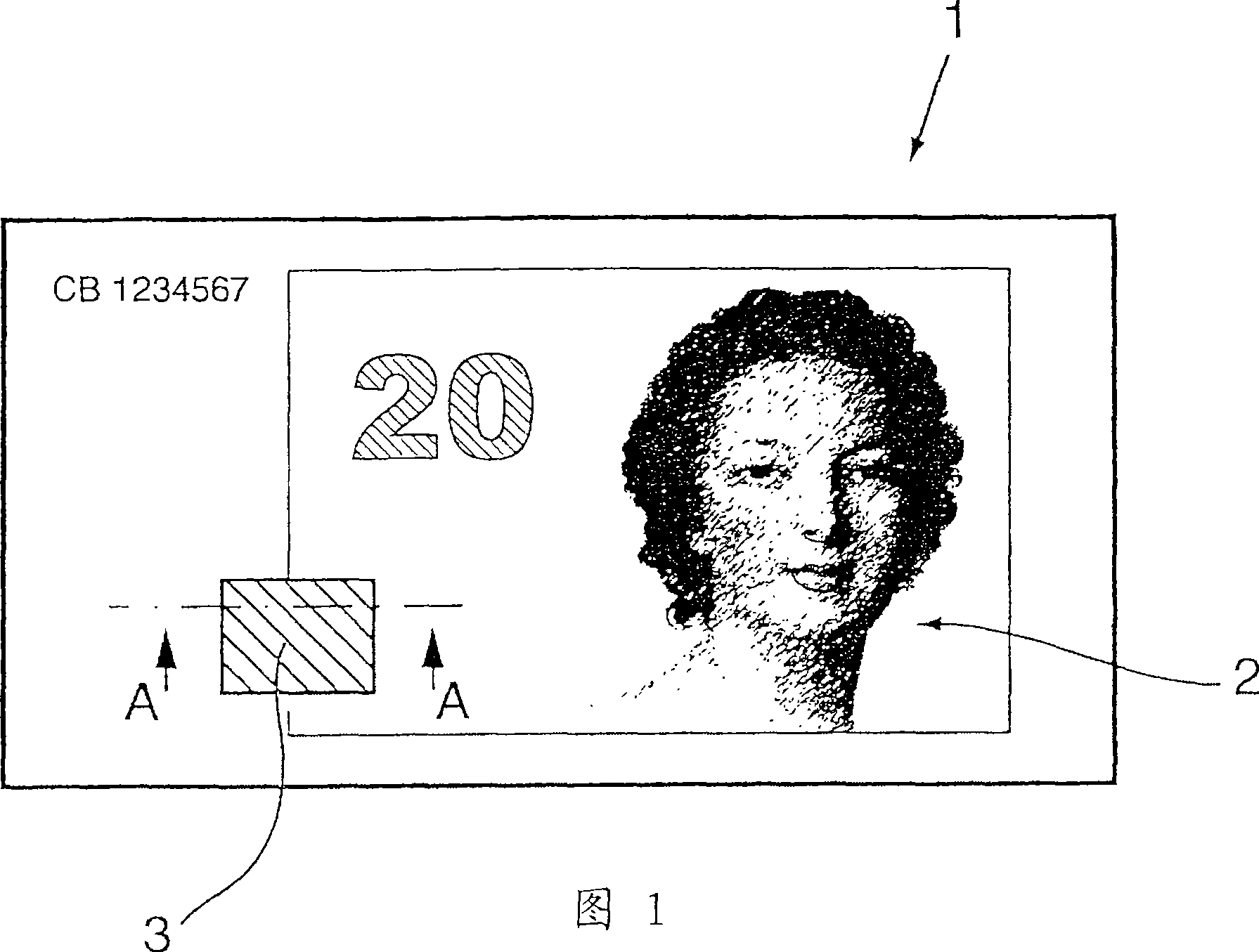
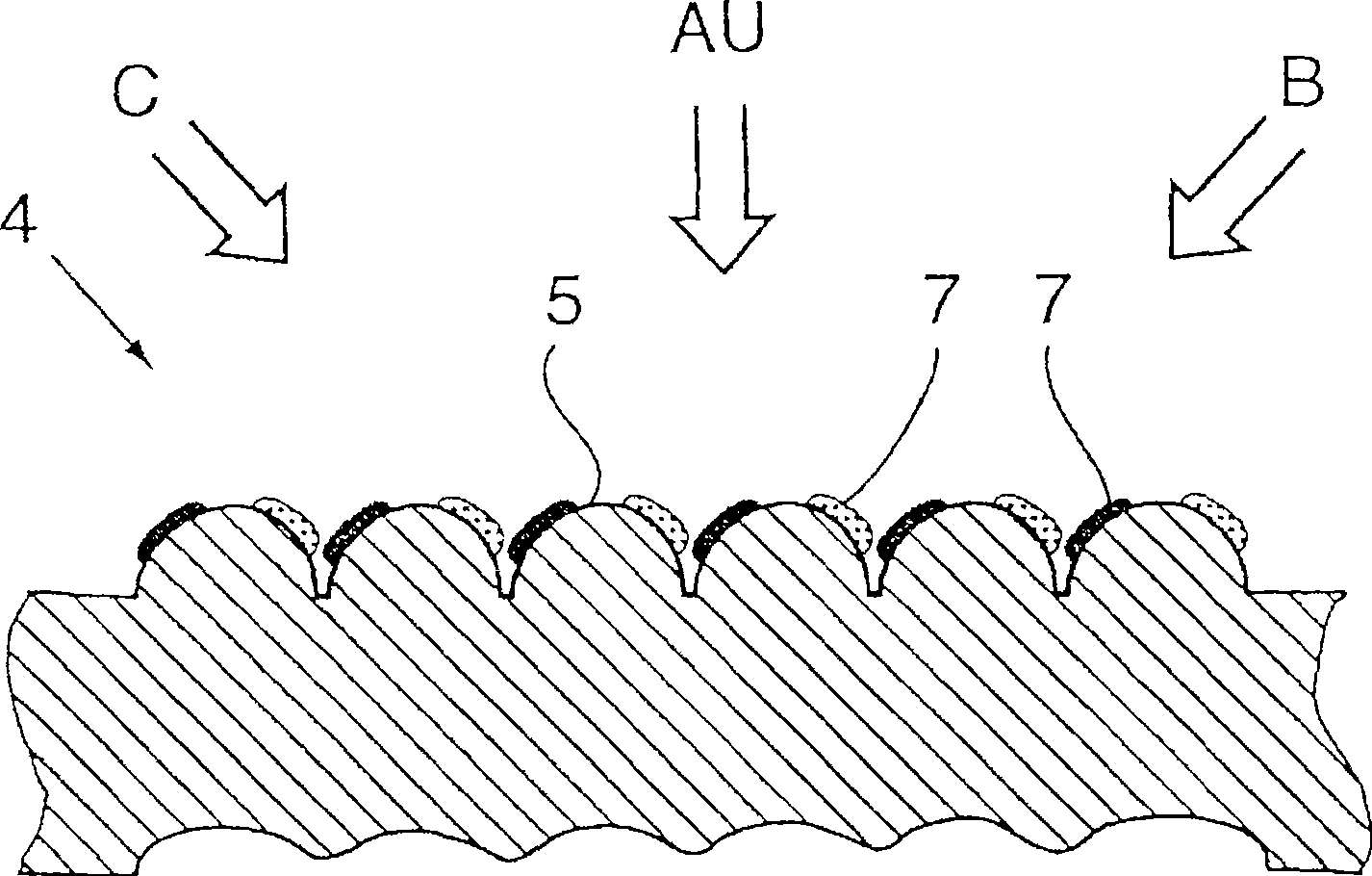
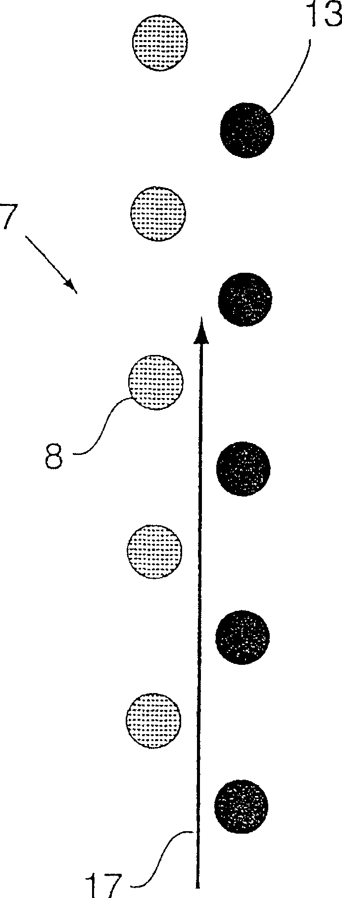
[0104] figure 2 A schematic cross-sectional view along line A-A (see Figure 1) is shown, and with image 3 and Figure 4 Together, an optically variable structure is shown in which the embossing structure 4 consists of regularly arranged uniform linear embossing elements 5 , ie configured as a periodic linear grid. The linear embossing elements 5 are provided with a coating 7 which is designed as a colored arrangement of non-linear basic elements. The individual colored faces of the non-linear basic elements are located on the edges of the linear embossed elements. The configuration of the linear embossing elements 5 as protrusions, preferably produced by embossing the data carrier, is clearly visible in a sectional view on the upper side of the data carrier. If the data carrier is mechanically deformed by means of an embossing tool, the underside of the data carrier exhibits a negative deformation. The deformati...
example 2
[0118] Example 2 ( Figure 15 and Figure 16)
[0119] Figure 15The coating 7 according to the invention shown in FIG. 16 comprises three types of non-linear basic elements 8 , 13 , 39 of different colors which are each arranged in the form of a grid with a constant grid width. Furthermore, basic elements 8 , 13 , 39 are each printed on a substrate (not shown in detail) in such a way that they form a colored basic element 52 . Corresponding to the regular arrangement of the individual basic elements, the colored basic elements 52 are also arranged in the form of a grid with a constant grid width. In this case, a colored basic element 52 is located in each grid cell 12 of the grid. The resulting regular arrangement of colored elementary elements 52 is divided into three subregions A, B, C in the preferred embodiment shown. Each subarea is provided with a not shown embossing structure 4 consisting of linear embossing elements 5 . The direction of the embossed structure 4 ...
example 3
[0120] Example 3 ( Figure 17a , Figure 17b, Figure 18a and Figure 18b)
[0121] exist Figure 17a The coating 7 shown in FIG. 17b is composed of three circular primitives 8, 9 and 13 of different colours, which also define a colored primitive 52 located within the grid cells 12 of the regular grid. Next, preferred directions are defined by the arrangement of the basic elements 8 , 9 and 13 , along which preferred directions the embossing takes place. In Fig. 17b the preferred directions 16, 18, 19 are identified and the embossed structure 64 along the preferred direction is schematically represented. The cross-section of the linear imprint element is triangular and corresponds to Figure 34a The cross section shown. The embossed structure 64 has a peak (amplitude) or apex 20 and a recess 21 therebetween. Thus, the non-linear elementary elements 8 and 9 are located on one edge of the non-linear embossing element when the coating 7 is embossed in the preferred direction ...
PUM
| Property | Measurement | Unit |
|---|---|---|
| Size | aaaaa | aaaaa |
Abstract
Description
Claims
Application Information
 - R&D
- Intellectual Property
- Life Sciences
- Materials
- Tech Scout
- Unparalleled Data Quality
- Higher Quality Content
- 60% Fewer Hallucinations
Browse by: Latest US Patents, China's latest patents, Technical Efficacy Thesaurus, Application Domain, Technology Topic, Popular Technical Reports.
© 2025 PatSnap. All rights reserved.Legal|Privacy policy|Modern Slavery Act Transparency Statement|Sitemap|About US| Contact US: help@patsnap.com


