Supercharge Your Innovation With Domain-Expert AI Agents!

Illumination system

一种照明系统、背光照明的技术,应用在照明系统领域,能够解决矩形光出射窗分布不够均匀等问题,达到改善光均匀度、改善均匀度的效果

Inactive Publication Date: 2009-04-29
KONINK PHILIPS ELECTRONICS NV
View PDF1 Cites 2 Cited by
  • Summary
  • Abstract
  • Description
  • Claims
  • Application Information

AI Technical Summary

Problems solved by technology

[0006] The disadvantage of this known lighting system is that the distribution of light on the rectangular light exit window is not uniform enough

Method used


Image

  • Illumination system
  • Illumination system
  • Illumination system

Examples


Embodiment Construction

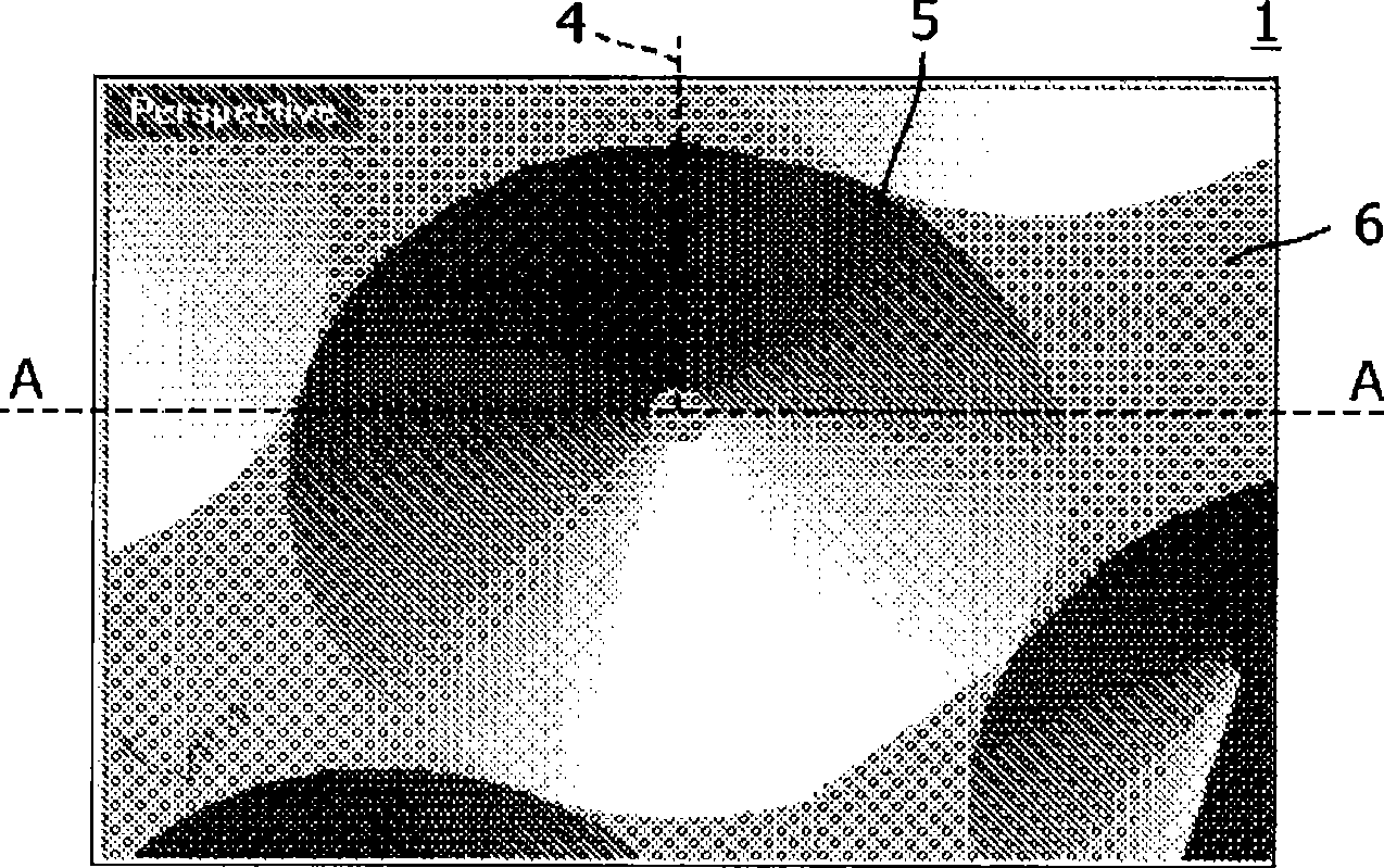
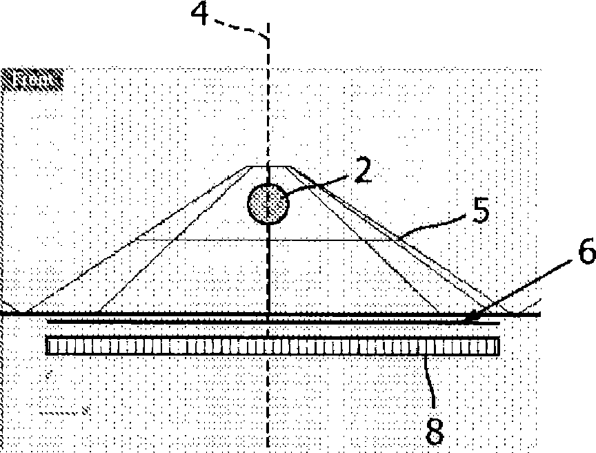
[0033] Figure 1A A plan view of a conventional lighting system 1 arranged in a rectangular array is shown. Each conventional lighting system 1 comprises a conventional cup-shaped reflector 5 . The cup reflector 5 is arranged around the light source 2 (see Figure 1B ). The light source 2 is located on a central axis 4 arranged perpendicularly to the light exit window 6 . The cup reflector 5 is a known reflector 5 which has a conical shape. This cup-shaped reflector 5 is generally used for so-called point sources, which are relatively small sources of light with three-dimensional emission characteristics. Known point light sources are for example light-emitting diodes, high-intensity discharge lamps such as halogen bulbs or even light-emitting windows which are light guides. The cup-shaped reflector 5 is arranged circularly symmetrically around the central axis 4 . In the radial direction, the shape of the cup reflector 5 can be concave, convex or as Figure 1A Shown is l...


PUM


Abstract

The invention relates to an illumination system (10, 101, 102, 40) for illuminating a display device (18). The illumination system (10, 101, 102, 40) comprises a conical reflector (15, 151, 152, 45) associated with the light source (12) for illuminating a light-exit window (16) arranged between the light source (12) and the display device (18). The reflector (15, 151, 152, 45) is arranged for reflecting light emitted by the light source (12) towards the light-exit window (16). The reflector (15, 151, 152, 45) is radially segmented into a plurality of reflector-cone segments (22, 25, 26). The plurality of reflector- cone segments (22, 25, 26) comprises at least one convex-cone segment (22) being convex shaped in a lateral direction with respect to a source axis (14) for lateral distribution of light emitted by the light source (12) over the light-exit window (16). The effect of the use of the convex-cone segment (22) is that light reflected from the reflector (15, 151, 152, 45) can be redistributed laterally over the light-exit window (16) in a predetermined manner which enables a uniform light distribution over the light-exit window (16). This is particularly beneficial for light-exit windows (16) having a polygonal shape (34, 35, 36).

Description

technical field [0001] The invention relates to a lighting system for illuminating a display device. [0002] The invention also relates to a backlighting system and a display system comprising the backlighting system. Background technique [0003] Lighting systems comprising a reflector for reflecting light emitted by a light source towards a light exit window of the lighting system are known per se. They are used in particular as lighting systems for (image) display devices, for example in projection systems. Such an illumination system may be particularly suitable for use as an illumination source in digital projectors (so-called projectors) for projecting images or displaying television programmes, films, video programs or DVDs or the like. Furthermore, such lighting systems are used for general lighting purposes, eg for large-area visual lighting panels, such as eg in signage, contour lighting and billboards. The widespread use of light-emitting diodes also makes thi...

Claims


Application Information

Patent Timeline
Patent Type & Authority Applications(China)
IPC IPC(8): F21V7/09F21Y101/02
CPCG02B5/10F21V7/09F21Y2101/02F21Y2115/10G02F1/1335
Inventor P·G·H·科斯特斯
Owner KONINK PHILIPS ELECTRONICS NV
Features
  • R&D
  • Intellectual Property
  • Life Sciences
  • Materials
  • Tech Scout
  • Unparalleled Data Quality
  • Higher Quality Content
  • 60% Fewer Hallucinations
Learn More