Electric tank cathode structure with conductive plate

A cathode structure and electrolytic cell technology, which is applied in the field of aluminum electrolysis, can solve difficult problems, improve aluminum liquid and other problems, achieve the effects of reducing horizontal current, improving stability and service life, and improving power efficiency

Active Publication Date: 2009-05-06
GUIZHOU BRANCH CHINA ALUMINUM IND +1
View PDF2 Cites 3 Cited by
  • Summary
  • Abstract
  • Description
  • Claims
  • Application Information

AI Technical Summary

Problems solved by technology

However, the change range of the cross-sectional size of the cathode conductive steel rod cannot exceed the internal range of the cathode carbon block. Considering that the tension of the cathode conductive steel rod on the two walls of the concave groove of the cathode carbon block at high temperature will increase, due to the influence of the cathode carbon block Due to the limitation of height and width, the change range of the cross-sectional size of the cathode conductive steel rod is not large, so it is difficult to improve the current distribution in the aluminum liquid and the cathode carbon block to the greatest extent.

Method used


Image

  • Electric tank cathode structure with conductive plate
  • Electric tank cathode structure with conductive plate
  • Electric tank cathode structure with conductive plate

Examples


Embodiment 1

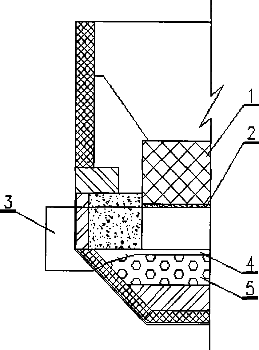
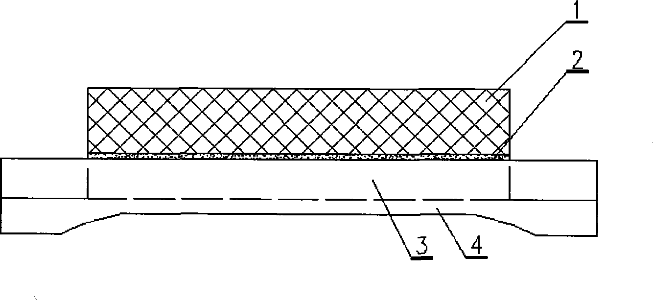
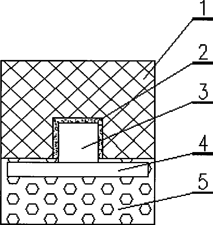
[0021] see figure 1 , The cathode structure of the electrolytic cell with conductive plate provided in this embodiment includes: cathode carbon block 1 , cathode conductive steel rod 3 , conductive steel plate 4 and anti-seepage layer 5 . Wherein, the cathode conductive steel rod 3 is located in the cathode carbon block 1; the bottom of the cathode carbon block 1 is provided with a steel rod groove matching the shape of the cathode conductive steel rod 3, and the cathode carbon block 1 is connected to the cathode conductive steel rod 3 through the steel rod groove; The conductive steel plate is located at the lower part of the cathode carbon block 1 and is located in the anti-seepage layer 5; the conductive steel plate 4 is connected with the cathode conductive steel rod 3 to conduct cathode current as a whole. The width of the conductive steel plate 4 is less than or equal to the width of the cathode carbon block 1 ; the thickness of the anti-seepage layer 5 is not less than ...

Embodiment 2

[0026] The difference between this embodiment and Embodiment 1 is that: the cathode conductive steel rod 3 is two steel rods centered on the cathode, and there is a distance between the two steel rods; correspondingly, the conductive steel rod 4 is two steel rods centered on the cathode. A steel plate, there is a space between the two steel plates, such as Figure 5 shown. In addition, the structure of the cathode of the electrolytic cell with the conductive plate is the same as that of Embodiment 1, and will not be repeated here.

[0027] The invention reduces the horizontal current in the aluminum liquid through the cathode conductive steel rod and the conductive steel plate, improves the electric energy efficiency, and improves the stability and service life of the electrolytic cell.


PUM


Abstract

The invention discloses a reduction cell cathode structure with a current-conducting steel plate and belongs to the technical field of aluminum electrolysis. The reduction cell cathode structure comprises a cathode carbon block, a cathode collector steel bar, a current-conducting steel plate and an impervious layer. The cathode collector steel bar is positioned in the cathode carbon block. A bottom part of the cathode carbon block is proved with a steel bar groove in a shape fitted with that of the cathode collector steel bar. The cathode carbon block is connected with the cathode collector steel bar through the steel bar groove. The current-conducting steel plate is positioned at a lower part of the cathode carbon block and in the impervious layer. The current-conducting plate is connected with the cathode collector steel bar into a whole to conduct a cathode current. The reduction cell cathode structure reduces horizontal current intensity in aluminum liquid, improves electric energy efficiency and improves the stability and service life of a reduction cell due to the cathode collector steel bar and the current-conducting plate.

Description

technical field [0001] The invention relates to the technical field of aluminum electrolysis, in particular to a cathode structure of an electrolytic cell with a conductive plate. Background technique [0002] In the aluminum electrolytic cell, the cathode conductive steel rod inside the cathode carbon block is connected with the cathode carbon block through the cathode tamping paste, and the current of the electrolytic cell is exported through the cathode conductive steel rod. In the prior art, the current distribution in the aluminum liquid and the cathode carbon block is mainly improved by changing the cross-sectional size of the cathode conductive steel rod. The specific embodiment is to design the middle of the cathode conductive steel rod as a large cross-section section, and design the two ends of the cathode conductive steel rod as small cross-section sections, and between the large cross-section section and the small cross-section section, a slope-type variable cros...

Claims


Application Information

Patent Timeline
Patent Type & Authority Applications(China)
IPC IPC(8): C25C3/08
Inventor 杨晓东周东方黄俊刘坚邹智勇刘铭耿培久杨溢孙康建
Owner GUIZHOU BRANCH CHINA ALUMINUM IND
Why Eureka
Try Eureka