Stacker crane body node-pin shaft connection mode and connection pin shaft

A technology of tower cranes and connection methods, applied to cranes and other directions, can solve the problems of inconvenient disassembly of tower body sections, difficult work intensity, and poor foothold for workers, and achieve saving of high-strength metal materials, large working space, and convenient operation Effect

Inactive Publication Date: 2009-05-13
SHENYANG JIANZHU UNIVERSITY
View PDF0 Cites 13 Cited by
  • Summary
  • Abstract
  • Description
  • Claims
  • Application Information

AI Technical Summary

Problems solved by technology

In order to ensure that the orientation of the positioning hole on the pin shaft is consistent with the orientation of the positioning hole used for the pin shaft positioning hole on the positioning sleeve, the two holes must be aligned before driving the pin shaft. If the hole position changes after driving, it must be withdrawn. It is difficult and work-intensive to re-drive the pin
[0005] 2. With this connection method, when the pin shaft is withdrawn, it must be punched from the inside of the tower body section. Because there are not all platforms in the tower body section, it is difficult for workers to stand on it, which brings difficulties to the disassembly of the tower body section. inconvenient
[0006] 3. The connecting pins used between the tower body sections are all made of precious high-strength alloy steel. If the headed pins are used, they must be turned with larger diameter materials, resulting in waste of materials

Method used


Image

  • Stacker crane body node-pin shaft connection mode and connection pin shaft
  • Stacker crane body node-pin shaft connection mode and connection pin shaft

Examples


Embodiment

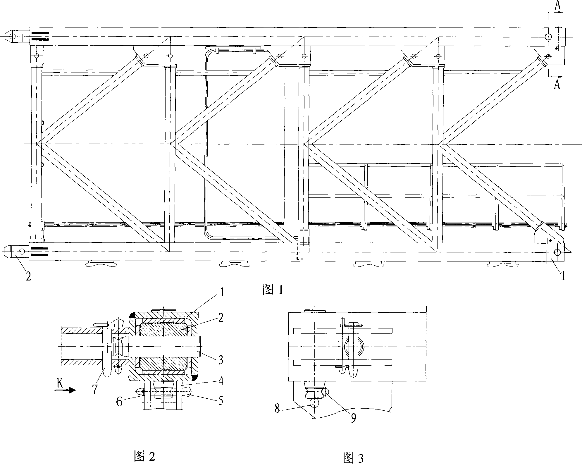
[0025] As shown in Fig. 1-Fig. 3, it is a schematic structural diagram of a tower crane adopting the tower body joint pin shaft connection method of the present invention, including the following steps:

[0026] 1. After putting the tenon 2 of the tower body into the inner hole at the end of the main branch 1, put the retaining pin 7 into the retaining pin hole 8 on the ear plate 4, and the position of the retaining pin hole 8 can be installed according to the needs. Depending on the length of pin shaft 3;

[0027] 2. Put the end of the connecting pin shaft 3 with the lock pin groove into the connecting hole of the main branch of the tower body section, and make the end of the locking pin part 12 of the connecting pin shaft 3 contact with the stop pin 7; The pin shaft 3 is driven to the predetermined position, and the lock pin groove on the connecting pin shaft 3 just matches the position of the lock pin hole 9 on the ear plate 4 at the end of the tower body section;

[0028]...


PUM


Abstract

The invention discloses a tower crane tower body section pin shaft connecting method and a connecting pin shaft, and belongs to the technical field of tower cranes. The the tower body section pin shaft connecting method comprises the following steps: arranging a tower body section tenon after an inner hole at the end part of a main branch; arranging a bumper pin in a bumper pin hole of an ear board; arranging the connecting pin shaft which has a lockpin groove end in a connecting hole of the main branch of the tower body section; causing the end part of the lockpin part of the connecting pin shaft to contact with the bumper pin; arranging the lockpin in a lockpin hole of the ear board to lock the connecting pin shaft, using a cotter lockpin to fix the lockpin; exiting from the bumper pin, and completing the connection of a pin shaft. The connecting pin shaft comprises a pin shaft main body, an introducing part and a lockpin part, wherein, the introducing part is positioned between the pin shaft main body and the lockpin part; the lockpin groove used for fixing the lockpin is formed on the lockpin part along a circumference direction. The lockpin groove is formed on the connecting pin shaft of the invention and is free from the direction restrain during the lockpin process; and the introducing part is positioned between the connecting pin shaft main body and the lockpin groove, thereby causing the lockpin groove not to influence the introducing process of the connecting pin shaft. The invention has the advantages of convenient installation and detachment.

Description

technical field [0001] The invention belongs to the technical field of tower cranes, and in particular relates to a pin shaft connection mode between tower body sections of the tower crane and a structural form of the used connecting pin shafts. Background technique [0002] At present, some of the tower cranes are connected by pin shafts, and some are connected by high-strength bolts. The tower body sections connected by tenons or fishplates are all connected by pins. This working method has high safety and reliability. It is enough to put the connecting pins in place and then position them. There is no pre-tightening force requirement; The method of connecting the tower body sections with high-strength bolts is simple, but the high-strength bolts must have an appropriate pre-tightening force to ensure work safety. [0003] At present, the pins used to connect the tower sections mainly have the following three problems: [0004] 1. Most of them are pin shafts with heads, ...

Claims


Application Information

Patent Timeline
Patent Type & Authority Applications(China)
IPC IPC(8): B66C23/26B66C23/62
Inventor 李斌李伟
Owner SHENYANG JIANZHU UNIVERSITY
Why Eureka
Try Eureka