
Hebel-verbinder

A technology of connectors and levers, which is applied in the field of lever connectors to achieve the effect of improving reliability

Active Publication Date: 2009-06-24
YAZAKI CORP
View PDF1 Cites 5 Cited by
  • Summary
  • Abstract
  • Description
  • Claims
  • Application Information

AI Technical Summary

Problems solved by technology

[0008] The present invention was made to solve the above-mentioned problems, and to provide a lever type connector having high reliability by preventing unnecessary deviation accidents in temporary locking of the lever

Method used


Image

  • Hebel-verbinder
  • Hebel-verbinder
  • Hebel-verbinder

Examples


Embodiment Construction

[0029] Hereinafter, embodiments of the present invention will be described with reference to the accompanying drawings.

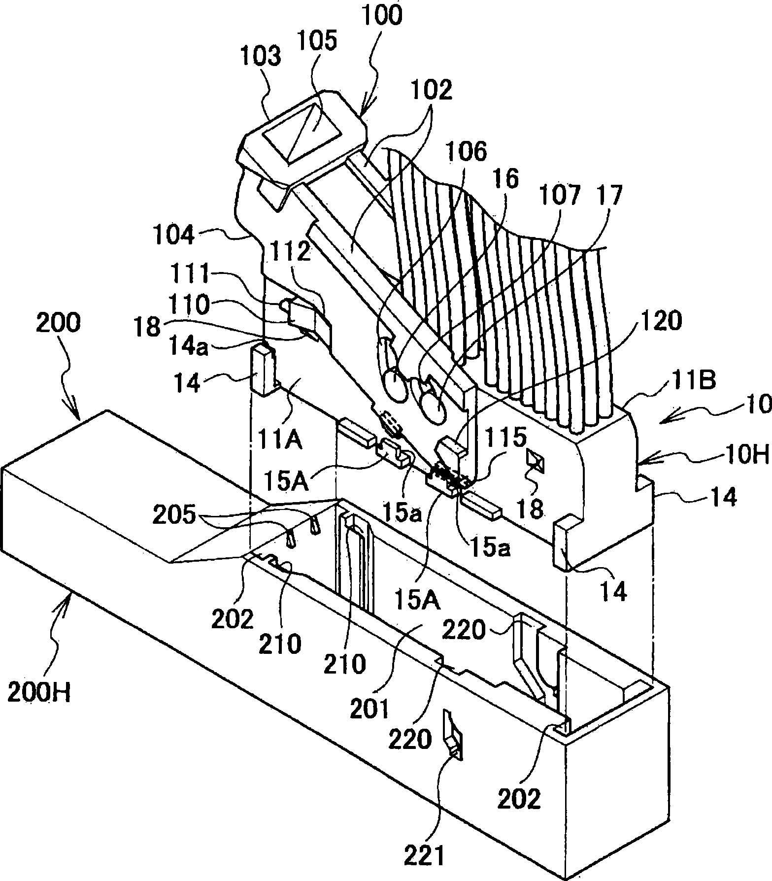
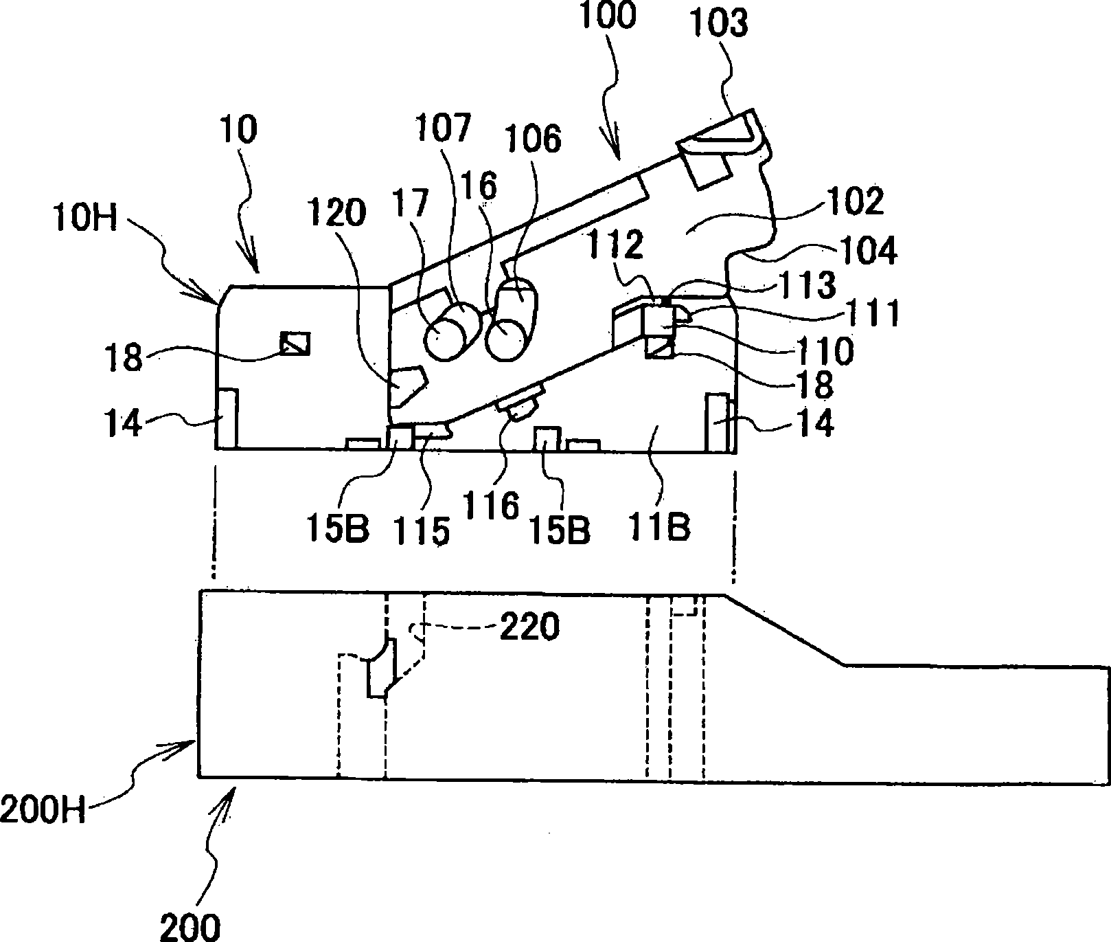
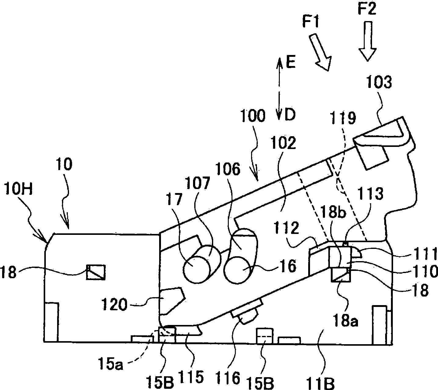
[0030] figure 1 is a perspective view showing a state of a lever-type connector before mating according to one embodiment. figure 2 is from with figure 1 Side view when viewed from the opposite side. image 3 is a side view showing a state where the lever is mounted on the male connector and held at the temporary locking position. Figure 4 is an enlarged view showing main parts. Figure 5 is a perspective view showing when viewed from the bottom of the lever. Image 6 is a perspective view showing the temporary locking arm when viewed from the bottom. Figure 7 is an enlarged perspective view showing the relationship between the clearance groove provided on the temporary lock arm and the protrusion. Figure 8 is shown when viewed from the opposite side, image 3 Side view of the states shown. Figure 9 is shown when force is applied to the lever t...


PUM


Abstract

Provided is a lever type connector for fitting connectors by swinging a lever 110, in which a lever side plate 102 is provided with a temporary locking arm 110. The temporary locking arm is provided with a bending restricting protrusion 113. When the temporary locking arm is deformed by applying excessive external force to a lever in a state where the lever before connector fitting is positioned at a temporary locking position, the bending restricting protrusion 113 restricts bending of the temporary locking arm in a temporary releasing direction (outward direction) by engaging with the inner face side of the lever side plate.

Description

technical field [0001] The present invention relates to a lever type connector capable of fitting or separating a female connector housing and a male connector housing with a small force by a swing operation of a lever. Background technique [0002] The lever-type connector has a lever that is swingably mounted on one connector housing of a pair of connector housings that are mated to each other, and is operated by swinging of the lever by being disposed between the lever and the other connector housing. The operation of the cam mechanism to help mate and separate the two connector housings. [0003] For example, the lever of the lever-type connector described in Patent Document 1 has a swing fulcrum portion (swing hole) on one end side of a pair of left and right lever side plates, which is connected to the adjacent connector housing. The swing fulcrum portion (swing fulcrum protrusion) of the body is fitted, and the lever of the lever type connector has a substantially U-...

Claims


Application Information

Patent Timeline
Patent Type & Authority Applications(China)
IPC IPC(8): H01R13/629
CPCH01R13/62938H01R13/62955
Inventor 松村薰鹤田哲广
Owner YAZAKI CORP
Learn More